Difference between revisions of "Equipment/Bird 43 Watt Meter"
| Line 9: | Line 9: | ||
|accessories=Inserts (Slugs)<!-- Any items associated with the equipment but not consumable, such as; drill bits, safety gloves, goggles, etc.. --> | |accessories=Inserts (Slugs)<!-- Any items associated with the equipment but not consumable, such as; drill bits, safety gloves, goggles, etc.. --> | ||
|reqtraining=Yes | |reqtraining=Yes | ||
| − | |trainlink=Must | + | |trainlink=Must hold an Amateur Radio license or be otherwise be proficient with RF<!-- If training is required, provide a link to training signup or contact page. Otherwise leave blank. --> |
|acnode=no | |acnode=no | ||
|owner=Radio Club<!-- Provide a link to owners members page if other than LHS --> | |owner=Radio Club<!-- Provide a link to owners members page if other than LHS --> | ||
Latest revision as of 23:44, 21 March 2019
Info
This item was kindly donated to the club by another radio Amateur.
Accessories
We have the following accessories for use with the Bird Watt Meter:
Inserts
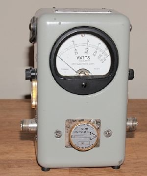
Inserts or "slugs" are inserted into the hole in the front of the meter. A signal is then passed through the meter via the two N-Type connectors. The source of the signal should be connected to the left hand connector, and the right hand connector must be attached to a suitable dummy load or antenna. In normal operation (Forward Power) the arrow on the insert should face to the right, however its possible to twist the insert so the arrow is facing to the left to measure reflected power. SWR can then be calculated from the two values if required.
You should always use the appropriate insert for the power and frequency you are using. If you are unsure on the power output, start with the highest rated insert for the frequency and then switch to a more appropriate value.
| Model Number | Frequency | Power Rating | Usage |
|---|---|---|---|
| 5C | 100 - 250 Mhz | 5W | Measuring VHF signals up to 5W |
| 100C | 100 - 250 Mhz | 100W | Measuring VHF signals up to 100W |
| 10D | 200 - 500 Mhz | 10W | Measuring VHF/UHF signals up to 10W |
| 100H | 2-30 Mhz | 100W | Measuring HF signals up to 100W |
| 250H | 2-30 Mhz | 250W | Measuring HF signals up to 250W |
Signal Samplers
The adjustable signal samplers allow you to tap into an RF signal allowing you to analyse the signal whilst operating. The attenuation of the sample signal can be adjusted.
| Model Number | Frequency | Power Rating | Attenuation | Usage |
|---|---|---|---|---|
| 4275 | 20 - 1000 Mhz | 1000 W | 35 to 80 dB | Tapping into VHF/UHF signals up to 1000 W |
| 4273 | 1.5 - 35 Mhz | 5000 W | -40 to 70 dB | Tapping into HF signals up to 5000 W |
