Equipment/Staubli/J11
< Equipment | Staubli
Jump to navigation
Jump to search
Revision as of 14:17, 17 February 2015 by JonRussell (talk | contribs)
The printable version is no longer supported and may have rendering errors. Please update your browser bookmarks and please use the default browser print function instead.
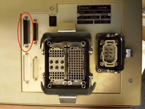
The J11 connector on the back of the Staubli controller contains the digital IO lines.
There are 6 relay outputs and 12 digital inputs. The connector can also supply 24v power.
The outputs are isolated normally open relay contacts, maximum rating at 125v @ 1A. Outputs 7 & 8 are used in the arm to control the gripper solenoids.
The inputs are opto-isolation 24v LED inputs. LOW = 0v-3v. HIGH = 10-24v. As they are LED opto-isolators, they only work with the correct polarity.
The outputs can be activated and deactivated in V+ like this :
SIGNAL 1                  // turns relay output 1 on
SIGNAL -1                 // turns relay output 1 off
SIGNAL 1,2,3,4,5,6        // turns relays 1-6 all on
SIGNAL -1,-2,-3,-4,-5,-6  // turns relays 1-6 all off
The inputs are used in V+ like this :
WAIT SIG(1001) // this pauses the V+ program until input 1 is activated and then continues.
The connector has 50 pins, in three rows. Refer to the following manuals for details and schematics :
- Page 9 – CS7 Electrical Diagrams
- Page 50 – CS7 User Guide
| Pin# | Description |
|---|---|
| 1 | O1+ (Output 1 relay contacts) |
| 2 | O1- (Output 1 relay contacts) |
| 3 | O2+ (Output 2 relay contacts) |
| 4 | O2- (Output 2 relay contacts) |
| 5 | O3+ (Output 3 relay contacts) |
| 6 | O3- (Output 3 relay contacts) |
| 7 | O4+ (Output 4 relay contacts) |
| 8 | O4- (Output 4 relay contacts) |
| 9 | O5+ (Output 5 relay contacts) |
| 10 | O5- (Output 5 relay contacts) |
| 11 | O6+ (Output 6 relay contacts) |
| 12 | O6- (Output 6 relay contacts) |
| 13 | I1+ (Input 1 positive) |
| 14 | I1- (Input 1 negative) |
| 15 | I2+ (Input 2 positive) |
| 16 | I2- (Input 2 negative) |
| 17 | I3+ (Input 3 positive) |
| 18 | I3- (Input 3 negative) |
| 19 | I4+ (Input 4 positive) |
| 20 | I4- (Input 4 negative) |
| 21 | I5+ (Input 5 positive) |
| 22 | I5- (Input 5 negative) |
| 23 | I6+ (Input 6 positive) |
| 24 | I6- (Input 6 negative) |
| 25 | I7+ (Input 7 positive) |
| 26 | I7- (Input 7 negative) |
| 27 | I8+ (Input 8 positive) |
| 28 | I8- (Input 8 negative) |
| 29 | I9+ (Input 9 positive) |
| 30 | I9- (Input 9 negative) |
| 31 | I10+ (Input 10 positive) |
| 32 | I10- (Input 10 negative) |
| 33 | I11+ (Input 11 positive) |
| 34 | I11- (Input 11 negative) |
| 35 | I12+ (Input 12 positive) |
| 36 | I12- (Input 12 negative) |
| 37 | NC / unknown |
| 38 | NC / unknown |
| 39 | NC / unknown |
| 40 | NC / unknown |
| 41 | NC / unknown |
| 42 | NC / unknown |
| 43 | 24v power |
| 44 | 24v power |
| 45 | NC / unknown |
| 46 | NC / unknown |
| 47 | NC / unknown |
| 48 | NC / unknown |
| 49 | NC / unknown |
| 50 | NC / unknown |
| Shell / Shield | Ground |

