Laboratory 24/Infrastructure
We moved in on Friday the 16/07/2010.
Landlord
The centre manager is Ted Kerr (07730 200 260). Area manager is Paul - ask Russ to email him.
Phone Service
There are two phone lines in the space:
- 020 7613 5391 (main phone, broadband)
- 020 7729 5134 (unconnected)
Phone service is provided through M-Line, who are a great little BT reseller. Any problems, ring them up and ask for Strachan (pronounced straw-n). Say Russ Garrett sent you.
Networking
Electricity
Initial meter reading: 251818 (16/07/2010) 254055 (12/10/2010)
Unit 23 readings, 2011/01/06:
red phase meter: no. L82A 52092 Reading: 13974.17 yellow phase meter. No. L82A 46898 Reading: 39426.37 Blue phase meter. No L82A 12901 Reading 30877.19
The new dist board (lower) is a Hager Invicta 63 TP&N 4 Way(JK04P)
Water
- No. 99T043076 Reading 00233.10323
- No. 99T043073 Reading 05402.62862
Alarm
We don't use the alarm controller, but we do use the 12V UPS and sensors for the door controller. Much of the existing sensors and cabling is still in place.
UPS/PSU
The UPS model number is 1381N.
- 12 volts, 1 amp output, 1.5 amp maximum (including battery charging)
- Mains LED (green) indicates that mains is connected. Extinguishes if disconnected from mains or mains input fuse is blown.
- Battery Stand-by LED (amber) indicates that unit is operating on battery stand-by. (does it? It's on all the time. seems to mean the battery is fine, unplugging the mains certainly powers the circuits off the battery, and the battery can't have been powering it the entire time...)
- Output Fault (red) indicates that output fuse fault or battery fuse fault. Further LED (red) on PCB shows battery fuse failure.
Sensors
Conveniently, stripping the alarm out has left lots of useful wiring all over the building. We're already using a pair of wires to trigger the door release; there are plenty more cables though, some even wired into useful sensors (PIRs and door open/closed magnets)
Notes
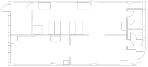
All measurements in cm
- Main Room: 400 x 1140
- First Room: 350 x 690
- Front bit: 55 x 110
- Quiet Room: 350 x 720
- Kitchen: 250 x 400
- Stratasys hole: 60 x 110
Lighting
- Unit 24 tubes are L36W/23 or F36W (commonly known as "4ft slim")
- Unit 23 tubes are F100W, except the kitchen which is F36W (as unit 24)
- No toilet lighting in unit 23
- The strip of lights in unit 23 second from unit 24 flicker
- Two starters are missing in unit 23 (one of the strips closest to unit 24)
- There are spare starters underneath the consumer unit (fuse box) in unit 24, but these are only suitable up to 65W and will not work in the large F100W lights in unit 23.
Power
- Socket on partition unit 24 (near quiet room entrance) needs replacement
- More 13A sockets needed in workshop, especially on north wall
- Heavy cabling needed from fusebox to planned cooking area
- Temporary power sockets near sink need sorting (unless kitchen plans make them redundant)
- The 3 phase power is currently not being monitored. We can raise awareness about the use of electricity in the space and generated interest in energy monitoring through this project: Energy Consumption Monitoring
Procedure for improving infrastructure
- Get quote for item(s)
- Discuss on irc/mailing list, optionally adding to the Infrastructure page
- Check finances with Russ or other Director
- Purchase item and obtain reimbursement / have item purchased directly from funds
- Install item
- Update the mailing list/wiki
Parking
The parking spaces are 36, 37 and 54
