Difference between revisions of "Project:AC Intensity Controller"
| (11 intermediate revisions by the same user not shown) | |||
| Line 3: | Line 3: | ||
== Theory == | == Theory == | ||
| − | The circuit converts the AC sine wave in to a square wave, and uses this to detect whenever the amplitude of the AC wave | + | The circuit converts the AC sine wave in to a square wave, and uses this to detect whenever the amplitude of the AC wave equals zero (the "zero-cross"). At that point the microcontroller switches the lighting circuit off, and at a time 0–10 milliseconds later switches it back on. This creates the illusion of reduced brightness. |
== Design == | == Design == | ||
| − | + | [[Image:AC Dimmer Board.png|frame|right|PCB v2, not yet tested.]] | |
| − | + | To detect the zero-crossing a zener diode (actually a diode and 3 LEDs) converts the AC waveform in to a square wave, which is passed in to an optoisolator (e.g. the CNY17-3) before being passed to the microcontroller. | |
| + | |||
| + | An otpocoupler (e.g. the K3020P) and TRIAC (e.g. the BTB06-600T) is used to switch the circuit output. | ||
| + | |||
| + | In my prototype I have been using an Arduino Uno, but intend to replace this with a [[Project:Nanode|Nanode]] once the PCB is complete and it is ready for enclosure. | ||
| + | |||
| + | [[Image:AC Dimmer Schematic.png]] | ||
== Application == | == Application == | ||
| − | This circuit has been designed for incandescent bulbs, unfortunately | + | [[Image:AC Dimmer v1.jpg|300px|thumb|right|AC Dimmer v1, does not work]] |
| + | |||
| + | This circuit has been designed for incandescent light bulbs, unfortunately generic ones are now obsolete and are in the process of being outlawed - however it should be possible to obtain specialist and decorative styles for the foreseeable future. It would also work on a custom array of LEDs powered directly from mains (but probably not an LED bulb). Regular compact fluorescent lamps are unsuitable, however dimmable CFLs may or may not be. | ||
| − | There are also potential non-lighting applications. For example, to | + | There are also potential non-lighting applications. For example, to add rudimentary temperature control to a soldering iron. |
Latest revision as of 13:25, 4 August 2011
I have been working on a circuit to control the brightness of an AC lamp, for the AlarmClock project.
Theory
The circuit converts the AC sine wave in to a square wave, and uses this to detect whenever the amplitude of the AC wave equals zero (the "zero-cross"). At that point the microcontroller switches the lighting circuit off, and at a time 0–10 milliseconds later switches it back on. This creates the illusion of reduced brightness.
Design
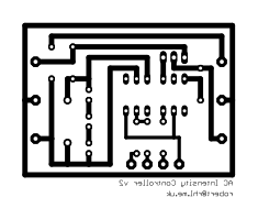
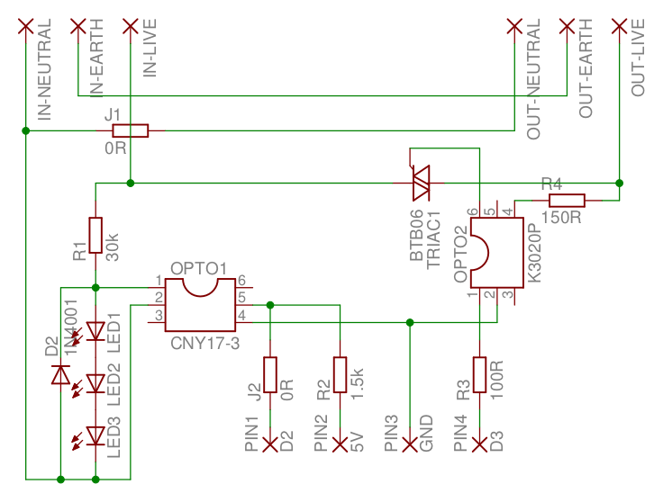
To detect the zero-crossing a zener diode (actually a diode and 3 LEDs) converts the AC waveform in to a square wave, which is passed in to an optoisolator (e.g. the CNY17-3) before being passed to the microcontroller.
An otpocoupler (e.g. the K3020P) and TRIAC (e.g. the BTB06-600T) is used to switch the circuit output.
In my prototype I have been using an Arduino Uno, but intend to replace this with a Nanode once the PCB is complete and it is ready for enclosure.
Application
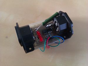
This circuit has been designed for incandescent light bulbs, unfortunately generic ones are now obsolete and are in the process of being outlawed - however it should be possible to obtain specialist and decorative styles for the foreseeable future. It would also work on a custom array of LEDs powered directly from mains (but probably not an LED bulb). Regular compact fluorescent lamps are unsuitable, however dimmable CFLs may or may not be.
There are also potential non-lighting applications. For example, to add rudimentary temperature control to a soldering iron.


