Difference between revisions of "Project:HSRDP"
m (→System diagram) |
(HSRDP status updates) |
||
| Line 19: | Line 19: | ||
=== Status === | === Status === | ||
| − | * [[Project:UMI_RTX_Robot_arm|Robot arm]] electronics replaced and working | + | * [[Project:UMI_RTX_Robot_arm|Robot arm]] electronics replaced and working, need current feedback and control lines added. |
| − | * The scooter base/drive-train has been fixed and | + | * The scooter base/drive-train has been fixed and the arm attached, though needs proper mounting as it's a bit wobly. |
| − | * The | + | * The drive train electronics are ready, they need to be installed together with the steering motor mounts (welding may be required) and halleffect sensors attached to the main drive motor with some magnets(ordered) |
| − | + | * Power distribution is being worked, will be running off 2 12v batteries | |
=== Updates === | === Updates === | ||
Revision as of 12:43, 7 February 2014
HSRDP - Hackspace Robotics Development Platform
HSRDP is an attempt to provide a robotics platform for the hackspace to allow people to experiment with higher level robotics functions.
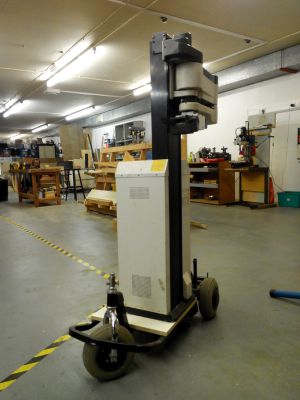
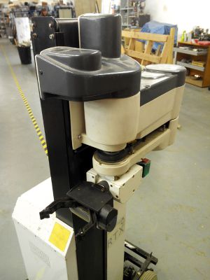
The plan is to sit our UMI robot arm on top of the mobility aid scooter. Plug it all into ROS with some sensors and allow people to make their own nodes for high level functions
It's part of the hackspace and collaborators are welcome, please get in-touch with Mentar (IRC) to find out what you can help. It's a great learning exercise for:
- the stuff that's required to get robot arm working
- Robotics (more higher level stuff!)
- ROS (point clouds, sensing, planning)
- arduino
- motor control
- battery management
Link to random photos from the ongoing project
Status
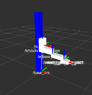
- Robot arm electronics replaced and working, need current feedback and control lines added.
- The scooter base/drive-train has been fixed and the arm attached, though needs proper mounting as it's a bit wobly.
- The drive train electronics are ready, they need to be installed together with the steering motor mounts (welding may be required) and halleffect sensors attached to the main drive motor with some magnets(ordered)
- Power distribution is being worked, will be running off 2 12v batteries
Updates
Update 6/1/2014
Mentar: Sourced the 2 sealed lead acid (AGM) batteries (Pride 12V 55AH) but they are heavily sulfacated thourgh lack of maintenance, tried charging one at 12V and it's responding albeit very slowly (only pulling 70ma at 13V), will need to build a desulfating circuit to bring them back to life.
Update 10/12/2013
Mentar: We mounted the arm on the scooter base. Implemented PID control for the motors, though yet to test it live.
People involved
This is a hackspace project and members are encouraged to participate so if you are interested just email the robotics group or get intouch with Mentar.
| Person | What is being done |
|---|---|
| Mentar, Tmlyk, pepelisu | Getting the robot arm functional |
| Stephen & Tom | Mobile base repair and control interfacing. |
| Paddy | Trimming the wheeled chassis, attaching steering motor |
TODO
Get the robot arm working (refer to page for breakdown)Repair the drive train, interface with the controller, make steering motor driverPrepare the wheeled chassis for the mounting of the robot armFit the robot arm to the base (arm facing towards one of the sides)- Figure out the battery management system and power distribution for the chassis and the robot arm.(24v battery and robot arm power and 5v for logic)
- Mount the steering motor and electronics.
Source a 24v battery (2 x 12v)- Add a kinect + other sensors
- Repaint/beautify the thing
Example uses
- Robotic buttler - Show people around the space, bring club-mate etc
- Robotic bartender - Party/event mode configuration, mix up drinks (this one is quite challenging)
- Telepresense - Self evident uses
- Guard bot - Could help with reducing cycle theft (need to film the thieves shitting themselves)
System diagram
<graphviz border='frame' format='svg' >
digraph rfboard{
  rankdir=TD;
  size="8,5!";

  arm_control [label="Arm control board (Mega)",shape=box];
  kinect [label="kinect",shape=box];
  brain [label="Laptop",shape=box];
  chassis_control [label="Chassis control (Uno)",shape=box];
  chassis [label="Wheeled Chassis",shape=box];
  robot_arm [label="Robot Arm",shape=box];
  steering [label="Steering motor",shape=box];
  kinect -> brain;
  brain -> arm_control;
  arm_control -> robot_arm;
  brain -> chassis_control;
  chassis_control -> chassis;
  chassis_control -> steering;
}
</graphviz>
Code
The code is stored at our github repository, let the project owners know if you want to be added


