Project:Infotec displays
Donated by Nottinghack, who have a project page with pictures. Further information posted by NortHACKton and Leeds.
Status
The screen on one side has been damaged and a roughyl 10x10 pixel area is dead.
Works fine apart from that.
We need to work out how to talk to it.
Update : we can send the time to it via the serial port, but don't yet know how to format the other commands.
Hardware
Photos by Akki
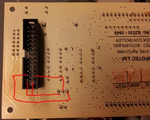
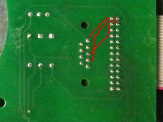
The serial port is exposed as a header on some master boards, in the comms ribbon cables, and as DE-9 connectors on the case board (where the power is split between the two units).
The header, with the register pin to the left, left-to-right, top-to-bottom is RX, TX, GND, GND.
Notes
Mark has done some work on the dumped rom, including extracting the fonts at Tom's suggestion:
A little more on possible protocols here: http://www.infotec.co.uk/index.php?page=communication
https://github.com/marksteward/Infotec/
The serial port is probably accessible using RS422 via the junction board that distributes power and signal to both clocks in the outer case. It is also available on the clock control board at RS232 levels (the signals are combined using combinational logic, rather than chosen with a switch). This is the small white 3-pin connector between the coin cell and the 2-pin connector for the front panel LED. Pins are ground, txd, rxd, counting from the edge of the motherboard towards the daughterboard. Protocol is 9600 8,n,1
The command
>PR#0#00#00,07,08#25,05,2012,2#3D<
sets the time to 00:07:08 (and, presumably, the calendar to 25/5/12 though we don't know how to display that at the moment). The tailing 3D is a checksum - the 2-digit hex representation of the XOR of all the preceding characters, starting with the '>'.
The clock seems to initially set itself up for 19200 baud serial port but later in the initialisation changes it to 9600.
Turning on DIP switch 8 and cycling power puts the clock in a display test mode.
Typing <>< into the clock causes it to sleep for a couple of seconds.
Command messages are in the format:
>inflags#sendresponse#cmdnum#serialtask#inbuf#args,args,...#checksum<
All except inbuf are in hex. Use 0 for inflags, 1 for sendresponse, 0 for serialtask, and cc to ignore the checksum
0x0 Set text
| Input | |
|---|---|
| serialtask |
|
| buf | message |
| arg0 |
|
| arg1 | ? |
| Output | |
>0#1#0#0#Hello##cc<
0xF4 Get date
| Input | |
|---|---|
| buf | |
| Output | |
| arg0 | date |
| arg1 | month |
| arg2 | year |
>0#1#F4####cc<
>00#80#01#1E,05,0A#37<
0xF5 Get version
| Input | |
|---|---|
| buf | none |
| Output | |
| flags | ? |
| arg0 | Major version |
| arg1 | Minor version |
>0#1#F5####cc<
>00#80#01#04,07#18<
Firmware
NEC 27 (25), which is almost identical to a 186, with register bank switching, DMA and a simple buffering (macro) system for interrupts. User manual and with opcodes and with chart.
| External bus | 8-bit |
| Clock speed | 8MHz? |
| DMA channels | 2 |
| Serial | built-in |
| Timers | 2 |
| Internal data area | 256 bytes based at xxe00 |
| Special functions | 256 bytes based at xxf00 |
Disassembly at http://github.com/marksteward/Infotec/.

