Difference between revisions of "Project:Nanode"
(added pic of my Nanodes on request) |
|||
| Line 8: | Line 8: | ||
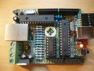
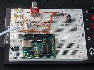
[[File:Nanode5_runs_blink.jpg|320px|right|thumb|First Nanode 5 runs code!]] | [[File:Nanode5_runs_blink.jpg|320px|right|thumb|First Nanode 5 runs code!]] | ||
| + | |||
| + | [[File:Nanode5_is_alive.jpg|320px|right|thumb|Newly-built Nanode 5]] | ||
== About Nanode == | == About Nanode == | ||
Revision as of 13:57, 9 June 2011
London Hackspace - Home of the 'Nanode Project'
A collaborative venture in open source hardware and firmware.
The Nanode homepage is at nanode.eu.
About Nanode
Nanode - a 30 second pitch
Nanode is an open source Arduino-like board that has in-built web connectivity. It connects to a range of wireless, wired and ethernet interfaces.
It allows you to develop web based sensor and control systems - giving you web access to six analogue sensor lines and six digital I/O lines.
It costs under £20 as an easy build it yourself kit. Nanode was designed with Hacking in mind.
Some Background
The Nanode is a low cost entry device aimed at network and Internet Connectivity projects.
It's name was originally derived from "Networked Arduino Node" as it essentially opens up the possibility of networking Arduino-like devices both to the internet, and locally using a mix of wired and wireless networks.
It has been conceived as an experimental platform, an enabling technology, which will allow applications to be developed at minimum cost and hassle.
It combines the functionality of the Arduino and an ethernet shield onto the one small board. This literally halves the cost of a net connected Arduino platform.
It has been designed with low cost hacking in mind and can be built easily for under £20 - so that it will appeal to those on a tight budget.
It uses the popular Arduino environment so will be familiar to many. It also accepts Arduino shields, and a wireless shield based on the popular RFM12 device is planned. This will open up the Nanode to wireless networking and creating bridges between wireless, and wired networks and the Internet.
Nanode consists of a small PCB which has the ATmega328 microcontroller, some glue logic, the ENC28J60 ethernet controller and a Magjack ethernet connector. The board only uses through-hole and DIL conventional components - so that it can be easily assembled by anyone who has basic soldering skills.
It makes an ideal project for a teaching workshop on web connectivity, and as such will appeal to Hackspaces for advanced Arduino workshops.
Nanode Applications
Nanode uses a Ethernet code library developed by Andrew Lindsay. Andrew has provided examples for a Twitter Client (using supertweet.net), a Pachube Publisher and Pachube Subscriber. Andrew has also developed code to allow DNS Client queries and sending UDP packet to a local network.
Nanode can be used as a micro web-server for simple home automation and control, be used to build web connected sensor networks and many other web connected applications.
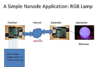
For those wanting to tinker with M2M applications, two Nanodes can communicate data or commands via a web data service such as Pachube.
Another unique feature is that several Nanodes can be connected together on a multidrop serial bus and used for distributed control tasks, such as energy montoring or home automation.
The wired network supplies communications and power and can be made from low cost 4 core telephone cable. 12V power can be distributed around this network and used to drive relays and actuators such as door locks.
Nanode provides between 10 and 12 input/output lines of which 6 can be analogue inputs for sensors such as thermistors or used for voltage and current measurement. Three of the outputs can be used for PWM control of motors, RGB lamps etc. Radio control servos are easily interfaced to the Nanode.
Individual Nanodes can communicate via this network back to an ethernet connected "Master" unit. With RS485 driver ICs, the Nanode can be adapted as a DMX lighting controller, MIDI network or other serial control system.
Nanode features an extra row of I/O pins - compared to the standard Arduino. This row of pins can be plugged directly into a breadboard and brings all of the ATmega I/O pins and power onto the breadboard. This greatly simplifies prototyping new applications on breadboard.
By removing the ethernet controller and Magjack, it becomes a very low cost Arduino "work-alike".
Nanode was inspired by the work of several key contributors.
Tuxgraphics - who wrote the original ENC28J60 code library
JeeNodes - for all things small and node like and routines for the RFM12 wireless
Ciseco - for the idea of stringing nodes together with a simple protocol
And many others, whose work has contributed to this project.
Nanode is an Open Source Project.
Open Source Collaborative Projects
The Nanode is possibly the first open source collaborative hardware design project at the London Hackspace- conceived, designed, manufactured and coded by Hackspace members - for Hackspace members. As an exercise in the design and building of a simple but useful microcontroller product, Nanode will introduce minimum cost web connectivity.
London Hackspace Custom Nanode
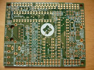
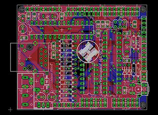
Here's a first draft of the proposed custom Nanode for the Hackspace. The Big H logo is a bit wonky, but we should be able to correct that with a bitmap import. Roger Light is working on this and other minor layout tweaks.
This new board offers several improvements over the first prototype.
The reset switch is vertically mounted on the edge of the board - so it can be pressed even though there may be a shield fitted.
The LED - again on the board edge, is visible with a shield fitted.
The local serial bus is now a 4 way screw terminal block for very easy hooking up with 4 way telephone cable which supplies 12V power and the Rx/Tx and ground lines. Remote nodes could draw up to 500mA total at 12V for powering actuators, motors etc.
Auto reset now added from serial interface - this uses Pin 6 of the FTDI cable and works with Arduino IDE.
Virtual USB Added. Vusb USB is done in firmware negating the need for a £15 FTDI cable. We then use the same programming tool as Metaboard uses - cool.
News
Moved to Project:Nanode/News.
How to Build a Nanode
Building a Nanode
The complete step by step build sequence is here Building a Nanode.
An older version for a previous design can be found on my blog
Parts List
This section needs updating to reflect the changes in Nanode 5 over the earlier prototype.
All parts are readily available. I recommend Cool Components in South London for several of the key items. Interested parties should try to pool component purchasing to access volume discounts.
   * 1 ATmega328 microcontroller (with Arduino bootloader) - CoolComponents £5.00 (£2.81 without bootloader)
   * 1 ENC28J60 ethernet controller - CoolComponents 1.99
   * 1 Magjack  - CoolComponents £1.99
The remaining parts were found to be considerably cheaper from Rapid Electronics giving a kit cost of £18 if parts are purchased in 10 off. This includes all parts, pcb, shipping and VAT.
   * 1 74AHC125 quad buffer 174-9617
   * 1 16MHz crystal 161-1761
   * 1 25MHz crystal 161-1783
   * 4 22pF ceramic capacitors 114-1760
   * 8 100nF ceramic capacitors 121-6444
   * 2 10nF ceramic capacitors 121-6435
   * 3 10uF electrolytic capacitors 945-1056
   * 1 7805 5V regulator 156-4483
   * 1 78L33 3V3 regulator 146-7768
   * 1 2K resistor 934-1480
   * 4 51ohm 1% resistors 934-3342
   * 3 270 ohm resistors 933-9353
   * 3 10K resistors 933-9060
   * 1 tact switch 181-3689
   * 2 8 way 0.1" SIL Sockets
   * 2 6 way 0.1" SIL Sockets
   * 1 6 way 0.1" right angle header
   * 1 2.1mm dc jack socket
   * 1 1N4001 diode
   * 1 3mm LED
   * 2 32 pin 0.1" header strips (for optional I/O connectors).
You will also need:
   * 1 Nanode pcb - available shortly to Hackspace members
   * 1 FTDI USB-serial cable - becoming a standard bit of kit for talking to microcontrollers.
   * or similar USB to serial converter such as Sparkfun/Cool Components
   * 1 CAT5 network cable to connect to router
Board Layout and Connectors
The nanode is, in essence, an arduino, with a hardwired ethernet chip, and several extra connectors / footprints for other useful bits and bobs.
It can do virtually anything an Arduino can do - in fact a part populated board is virtually half the cost of a cheap Arduino.
It has other features which we will slowly try to get sensibly documented here:
Pin Outs
| atmega328 pin | arduino name | other connections |
|---|---|---|
| 2 | D0 | ftdi rx, (ExtRx - only if tristate buffer is enabled by jumpered Dig 4 LOW) |
| 3 | D1 | ftdi tx, (ExtTx - only if tristate buffer is enabled by Dig 6 LOW) |
| 4 | D2 | ethernet and wireless RFM12B interrupt (INT 0) via trisate buffer/level shifter |
| 5 | D3 | USB D+ (And INT 1 from Vusb) |
| 6 | D4 | USB D- |
| 11 | D5 | (free) |
| 12 | D6 | etx enable / red LED LED comes on when LOW and this 'node is accessing the local bus |
| 13 | D7 | MAC address SCIO |
| 14 | D8 | effectively, slave select for the ethernet (ENC28J60 /CS) |
| 15 | D9 | IC7 slave select (if installed) |
| 16 | D10 | external wireless slave select |
| 17 | D11 | MOSI for all peripherals |
| 18 | D12 | MISO for all peripherals |
| 19 | D13 | SCK for all peripherals |
Other Main Features
Ethernet Connection
The two single-colour LEDs on the ethernet connector aren't connected directly to the Nanode; they are controlled from the ENC28J60 ethernet chip. However, you can set them to any arbitrary values you wish using the ethernet controller's registers.
(The schematic shows a single-colour LED and a dual-colour LED; this is a terribly minor bug in the schematic; the actual jack has two single-colour LEDs.)
Local Bus
The "local bus" communications are on the etx and erx screw terminals in the lower-left corner of the board. The lower terminal is etx (the labels are invisible once the board has been soldered together). When D9 is *low*, the output from D1 goes to both the FTDI cable connector and the etx terminal. Similarly, the input from both the ftdi cable and the erx pin comes in on D1 if the /RXEN pin is *low*. (Obviously, using both at once will be very confusing.) Note that /RXEN is not wired to the Nanode; it's recommended that you put a jumper between D4 and the /RXEN pin if you want to use the local bus. Contrarywise, you could just jumper it to GND if you don't want to use the FTDI connector, or if you can handle bus arbitration on a higher level... there's more then one way to do it.
The screw terminal connector can be used to connect Nanodes to the local wired serial bus. Using cheap 4 core phone cable, carry +12V, 0V, ExtTx, ExtRx, and connect many Nanodes together in a wired network. Standard phone cable will easily carry 500mA at 12V, so this bus can be used to power actuators such as relays, servos, door latches, displays and any other stuff that needs low power DC.
A slave Nanode does not need its Magjack or ethernet controller - so this saves about £4 in build cost and frees up the SPI bus as useful digital I/O.
Wireless Port
This version 5 Nanode has been designed to take a low cost RFM12 wireless transceiver breakout board from JeeLabs, which plugs directly into an 8 pin SIL socket in the middle of the top edge of the pcb. This can either be 433 or 868MHz. It runs on 3V3 and all code is compatible with the JeeLabs code.
Vusb Port
Vusb was devised by Metalab in Vienna to make a very low cost way of programming Arduino like devices and AVR processors. It runs a virtual USB client in the bootloader firmware allowing you to program the board with just a USB lead and no FTDI device. This is now working and can be used to load arduino sketches (Artag). Some additional polish is needed.
MAC Chip
The Microchip 11AA02E42 is a 256 byte EEprom which contains a unique MAC address and the rest of the array is free for user storage - such as configuration data. These chips are available up to 4K byte - and could be used for holding web pages, or bitlash scripts as a non-volatile extension to the internal EEprom. Needs special driver code to access - still under development (as of 7/6/11)
SPI Memory
An uncommitted SPI memory which can be SRAM, FRAM or dataflash/EEprom. I have used a 23K256 32K x 8 SRAM here - and can read it at approximately 100,000 bytes per second. Using this particular SRAM needs the whole board to be powered at 3V3 - which is a minor modification involving invasive surgery.
Servo Port
+5V, 0V and Digital 4 brought out on 3 adjacent pins for conveniently driving a single model servo.
Can also drive the "Modern Device" serial LCD display controller boards via a 3 wire servo cable.
Arduino Shield Connectors
Perversely Pitched to accecpt most Arduino shields. Watch out what you/they do with digital 8 and digital 10 or your ethernet may not work. Also you may have to use "extended headers" to raise the shield clear of the magjack and 7805 regulator metal work
Board Layout
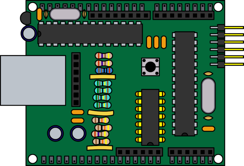
Matt Gaffen has offered to do another really nice Nanode graphic to go here to show where all these connections are.
Connectors
Nanode is not short of connectors. As well as the Arduino shield connectors it has its own set aimed at different features
With the magjack on the left, these ports are along the top edge of the pcb. You can fit a single 0.1" header (or extended headers) and insert all of the useful Nanode I/O directly into a bread board.
Analogue 2 Connector (from left to right)
Pin Name
- +5V
- Analog Input 5
- Analog Input 4
- Analog Input 3 | This is the same analogue port lines brought to the top edge of board with +5V and 0V for convenience
- Analog Input 2
- Analog Input 1
- Analog Input 0
- OV
Wireless& SPI Connector - accepts a Jeelabs RFM12 breakout board directly. (from left to right)
Pin Name
- +5V
- 0V
- SCK
- MISO
- MOSI
- SS (digital 10 in this case)
- INT
- 3V3
Digital 7- 0 Connector (from left to right)
Pin Name
- Digital 7 |
- Digital 6 |
- Digital 5 |
- Digital 4 | Just Like Arduino "Digitals"
- Digital 3 |
- Digital 2 |
- Digital 1 |
- Digital 0 |
Then for the bottom row of connections - starting at the 7805 regulator and working left to right
- 0V
- +5V
- Digital 4 (Use this and 0V, +5V (above) to plug a 3 pin servo cable straight in
- /RxEN - jumper this to Digital 4 if you want to use the local serial bus instead of FTDI cable
- ETx - External Tx - buffered by 74125 tristate buffer and only enabled if Digital 6 is LOW
- ERx - External Rx - buffered by 74125 tristate buffer and only enabled if /RxEN (jumper it to Digital 4) is LOW
- /RESET |
- +3V3 |
- +5V | These 6 are just like Arduino "Power" connector
- 0V |
- 0V |
- Vin (+12V to 7805 regulator) |
- (Then there is a gap here)
- Analogue Input 0 |
- Analogue Input 1 |
- Analogue Input 2 | These 6 are just like Arduino "Analogs" connector
- Analogue Input 3 |
- Analogue Input 4 |
- Analogue Input 5 |
Current Build Files
The latest Nanode 5 build files have been put up on Thingiverse .
Earlier versions on Thingiverse are really for reference only and should not be treated as current. The following data relating to versions 2 and 3 is for information or historical reference only:
The first prototype Nanode 2j had a couple of minor layout bugs, these have been corrected in 2l. The EagleCAD pcb files have been uploaded to Thingiverse as a starting point, but potential users should read the bug-list on the schematic page.
I've now corrected the pcb errors and made some improvements. The Version 3d files are here on Thingiverse
1. Fixed the incorrect connections on the Magjack
2. Moved the reset switch to edge of board and allow for a vertical switch which can be pressed even if shield is fitted.
3. Moved the LED to board edge so that you can see it
4. The local comms bus and power now routed to a 4 pin screw terminal for easier connection
5. Added auto reset capacitor C17 on pin 6 of FTDI connector
6. Added pull-up resistor to /RXEN so that it defaults to FTDI connection
7. Removed surplus connectors
8. Added a H as a place keeper for the proper Hackspace Logo. Actual logo courtesy of Roger Light from Nottinghack.
9. Added text "London Hackspace NANODE 5" and (c)2011 Arbour Wood Ltd. (Ken's design firm).
10. Improved position of 3V3 decoupling capacitors on ENC28J60
11. Analogue input connector J12 now has GND pin
12. Implemented Virtual USB with connector P7 on end of the pcb - saving cost of FTDI cable!!
14. I think that these would be so cool on blue pcb board with white Hackspace "H" Logo
Example Applications
Nanode Applications
Now moved to the Nanode Applications page.
Projects "In the Wild"
- Nanode controlled RGB LED Lamp, with simple serial command interpreter - see my blog here.
- 6 channel temperature monitoring using Pachube - email Ken via LHS list for code.
Add links to your own projects...
Brainstorming
This section is for all potential applications and wild ideas of what can be done with the Nanode.
Some other ideas planned or on the wish list: - please feel free to add your own ideas/wishes. If you want to contribute to any of these ideas - go ahead!
1. A low cost, plug-in wireless shield using popular RFM12 wireless module would allow the Nanode to form the basis of wireless networks - as well as have compatability with JeeNodes and some of the CurrentCost Energy Monitoring devices. I'm currently working on this shield layout - Ken
2. Use of virtual USB to eliminate the FTDI cable - implememted on Version 4. Hardware done on V3 and V4 - firmware & bootloader need to be tested.
3. A serial configuration program. Allows the IP address and other configuration parameters of the Nanode to be easily programmed from PC/MAC. Nanodes could be given unique MAC and sub-address. Sam Carlisle and Matt Gaffen worken on this at the Pachube Hackathon.
4. A position for a surface mount SPI memory (either RAM or EE) on the underside of the board to allow web page storage or much needed RAM buffer space. Microchip 23K256 adds 32K RAM for £1. One SMT device as an option should be acceptable to most constructors. Done - on V4, will also work with non-volatile FRAM memory. Provision on V4 for Microchip 11AA02E48 - unique MAC address from tiny 3 pin chip. - Ken
5. An energy monitoring shield for electricity and gas meter pulse counting - working on this with Glyn Hudson and Trystan Lea of openenergymonitor.org. -Ken
6. Define a simple serial network protocol to allow Nanodes to communicate
7. Improved firmware to allow easy access to and from Pachube for data exchange
8. Firmware to allow MQTT messaging
9. Experiments to define maximum data transfer rates across the various networks
10. Dedicated web forum / wiki for all Nanode co-developers: http://nanode.eu
As a simple example, a Nanode could read up to 6 analogue sensors, connected to its ADC inputs - such as temperature sensing thermistors or LM35 thermometer ICs. These temperature sensors are located in different rooms of the house, or outside, or on the hot water tank. Between them they give an indication of the state of the home heating. The temperature readings are published up to a Pachube feed, where they can be accessed by other devices. A Nanode subscribing to the feed reads the temperature data as a CSV string, strips out the numerical data and acts on its content. For example controlling a user display, operating relays which control the boiler for heating or hot water as it is required.
The CSV format which Pachube uses is flexible enough to cope with many types of data, or even direct numerical commands. A string of comma separated, numerical commands passed up to Pachube could be simply interpreted by any subscribing Nanodes to perform a specific action. The first number could be the address of the Nanode which you want to command, for example the one which controls the boiler relay.
Openenergymonitor have developed some very low cost Arduino based devices to read electricity and gas meters. One of these will shortly be released as an Arduino shield and could use the Nanode as its connection to the net.
The other main application of the Nanode is in Master/Slave wired networks. Several Nanodes are connected to a wired serial bus and distributed about the environment where they run sensing or control tasks - such as a home automation system or DMX lighting control system. Each slave can be addressed individually by a Master controller, which then connects via its ethernet connection to the web.
Slaves could store sensor readings in RAM (limited to 2K on the '328) and periodically be polled by the Master device to connect to the serial bus and upload its data. Data could be recorded straight off the serial bus using the Openlog serial data logger concept from Sparkfun Electronics. The Openlog code runs nicely on an Arduino fitted with a SDcard shield, so could be run on the Master Nanode. The Master could act as a SDcard based file server or storage to the serially connected slaves.
Help and Further Documentation
Questions & Answers & Feedback
If you have any queries - please put them here under the relevant section heading.
HARDWARE
Some recent Q & A
solexious Before I wade through the wiki page, how come the nanode doesn't have an ftdi chip?
Adding a FT23RL to the design would have added at least £3.25 to the cost (100 off) and as has been stated it is a surface mount device which the majority of assemblers would lack confidence in fitting to the board. One of the key features of the Nanode design is that anyone can put it together without specialist solderiing skills, moving to SMT devices would make it non-viable for DIY assembly.
As the board is fairly tight for real-estate it would have been difficult to find room for one.
It was assumed that the Nanode would be deployed into control and monitoring systems into which only occasional access to the UART would be required from a laptop - so a FTDI lead was deemed to be sufficient.
The FTDI lead is way over-priced, so the intention is to produce a ready built FTDI programming dongle for about half the cost of a FTDI lead.
Update 12/5/11 Version 5 is the latest Hackspace Version - see above for list of changes.
PCBs expected at the end of May. A Nanode Build and Applications Weekend is planned for June 4th / 5th.
Update 15/4/11
Roger Light has ported the Hackspace Logo and is making minor tidying operations to the pcb tracking.
See Thingiverse for earlier board files.
Is the local bandwidth between two nanodes enough to create an ethernet bridge in software? -- Answer to myself: the multidrop bus is in the range of 9600 baud.
The ATmega328 is not limited to 9600 baud serial. If the distance between nodes is short then 115,200 baud may be possible. You could also connect nodes together with I2C or SPI over short distances. Ken
PCBS & KITS
Can non-members join the PCB batch?
Yes - but note that we are currently only offering a full kit consisting of pcb and all components for £18.00. The first batch of 40 should be available in early May. We will hold a weekend workshop "Nanode Build and Test" session to coincide with the kits arriving.
Bare boards may be available at a later date, but for now the £18 kit is the only option being offered. A small donation to the Hackspace from non-members would be appreciated. Ken
PROGRAMMING
Will the Vusb code fit in the bootloader to allow it's use for programming the board ?
By all accounts, adding Vusb will make the Nanode appear like a Metaboard - which can be programmed by adding their programmer to the toolsuite in the Arduino IDE. Programming should then be a case of picking the Metaboard option. Metaboard Ken.
Today's build of the loader is 1994 bytes long out of a possible 2048. It may be possible to add a few minor features.--Artag 22:47, 8 June 2011 (UTC)
CODE EXAMPLES
There's a 'readpachube' example in Andrew's 1.6 software release, which I presume is the Pachube subscriber. I can't see a publisher though - is that available from somewhere else ?
I have developed a Pachube Publisher and matching Subscriber which allows serial CSV text strings to be sent from one Nanode to another via my Pachube Feeds 9675. If you put a request email to the Hackspace mailing list,I will send you the files. You will need to add your own Pachube API Key. I've more detail on my blog here. Ken
