Project:Nanode/Applications
Before You Start
Nanode uses an ethernet library which was written specifically to drive the ENC28J60 ethernet controller.
This device is used on several similar designs, and it must be noted that the library needs to be tailored so that it correctly addresses the ENC28J60 via digital pin 8, and not pin 10 as used in some ethernet shields.
To do this look at the DHCP test sketch and identify the line
es.ES_enc28j60Init(mymac);
for Nanode version 5 users this should be changed to:
es.ES_enc28j60Init(mymac,8);
Pin 8 is the pin used by the microcontroller to select the ENC28J60 for the SPI bus and if you don't add this, the MCU won't be able to communicate with the ENC28J60.
If you forget to do this, when you first power up there will be a message
ENC28J60 Version 0
This will appear as ENC28J60 Version 7 after the change has been made and you will know that all is well.
We are in the process of creating a Nanode specific library that defaults to pin 8, so this change will not be needed in the future.
Nanode and Pachube - Upgrade to a Free Pachube Pro Account
Nanode owners who have bought Nanodes through the London Hackspace may contact Pachube to receive a free Pro Account.
Pachube have been very supportive of the Nanode Project with this generous gesture to get a lot more Nanodes using Pachube and developing interesting applications. Contact Ed Borden at the email address below to collect your free Pro user account.
From Ed Borden, Pachube, New York.
"We are really excited about this project here at Pachube. We want to give our full support to anyone who has the gumption to take this thing and pull it along to the next level. I don't care if you haven't tested the first run yet! :) Full steam ahead!
For any of you guys on this list who bought a Nanode from Ken and want to connect it up to Pachube, drop me a line with your username and I'll upgrade your account to Pro. And when you do something awesome that you want the world to know about, tell us about it!"
edborden at pachube dot com
Testing Nanode
The ATmega328 microcontroller supplied with the kit has a specially modified version of the Arduino bootloader pre-programmed into it.
Arduino usually has a LED wired to Digital pin 13, but in Nanode, digital 13 is in almost constant use as the SPI Clock.
So in the Nanode bootloader, the LED flashing function has been altered so that it flashes the red LED which is wired to digital pin 6.
If all is well with your Nanode board, the Red LED should start flashing about 2 seconds after the power (from USB or FTDI cable) has been applied.
If it does not flash, check for faults such as missing soldered joints or the LED incorrectly inserted.
Applications
Quick Tutorial- 4/6/11.
1. Download and Install Arduino Environment http://arduino.cc/en/Main/Software Mac users: mount the dmg and drag arduino into Applications folder. Windows users: open the arduino-0022 folder and run Arduino.exe Ubuntu users (tested on 10.10): sudo apt-get install arduino
2. Download FTDI Cable Drivers
Plug in the FTDI programming cable.
- Windows users: When prompted to install drivers, point the installer to the arduino-0022/drivers directory
- Mac users: mount the arduino installation dmg and double click on the FTDI install package at the bottom of the window. In Arduino application menu/Tools/Board/ select "Arduino Duemilanove or Nano w/ ATmega328" and menu/Tools/Serial Port "/dev/tty.usbserial-A400f2he"
- Linux users: if you are using a 'modern' ubuntu or debian install (from my experience) the FTDI cable should be plug and play, type dmesg into terminal to check for the device mount point, mine is: /dev/ttyUSB0
3. Download EtherShield Libraries
Download here: https://github.com/thiseldo/EtherShield
- Change the downloaded folder name to "EtherShield" and place in Arduino/libraries/ folder
- Mac users: make a folder called "libraries" in Documents\Arduino\ then place the EtherShield folder into the newly created libraries folder.
- Windows users: place the EtherShield folder into arduino-0022\libraries\
- Linux users: place the EtherShield folder into arduino-0022\libraries\ (or /usr/share/arduino/libraries/ ?)
4. Run the EtherShield_DHCPTest
Arduino: File > Examples > EtherShield_DHCPTest
- In the source code, change MAC address to something random :) e.g. change the last two digits "??" to the two digit number written in pen on the bottom of your Nanode:
static uint8_t mymac[6] = {0x54,0x55,0x58,0x5F,0x01,0x??};
- (for Nanode version 5 users) On line 57, change
es.ES_enc28j60Init(mymac); to es.ES_enc28j60Init(mymac,8);
- (for Nanode version 2- older prototype boards) On line 57, change
es.ES_enc28j60Init(mymac); to es.ES_enc28j60Init(mymac,10);
Be sure to set the baud rate at 19200.
EtherShield Library and Examples
Once you have built your Nanode and got the red flashing LED which shows that all is well with the ATmega328 microcontroller and it's bootloader programme, it is now time to test the rest of the system, which includes the ENC28J60 ethernet controller and its interface through the magjack connector to the ethernet port.
Conveniently, Andrew Lindsay, has provided some simple example to accompany his Ethershield Library. It is common practice amongst Arduino libraries to provide accompanying tried and tested code examples, which are loaded as part of the library folder.
First you need to download and install the EtherShield library from GitHub
https://github.com/thiseldo/EtherShield
Make sure you have Arduino 0021 or better still 0022 installed, and press the download button. This will download the library as a .tar or .zip format into a temporary folder. Unzip the contents of this zip and put it in a folder named "Ethershield" within the Arduino/libraries folder.
(Remove any previous version of Ethershield library - as this causes code compilation problems).
When you restart the Arduino IDE, it will find this new library and add it into the Examples on the Files menu.
DHCP Test
Open Arduino IDE and select File/Examples/Ethershield/EtherShield_DHCPTest
Scroll down the code until you find the lines
 Serial.println("Init ENC28J60");
 es.ES_enc28j60Init(mymac);
As this routine is used for several hardware implementations that use the ENC28J60, we have to make one small change to suit the Nanode. Nanode uses Digital 8 to select the ENC28J60 - so change this code to
 Serial.println("Init ENC28J60");
 es.ES_enc28j60Init(mymac,8);
Press the save button from the tool bar - a downward pointing arrow to save this change for later.
Now make sure that you have the correct serial port connected from Tools/Serial Port and that the Board type has been selected as Arduino Duemilanove or Nano w/ATmega 328 - the second option down the list.
You may now compile and upload the code to the Nanode using the Upload button (right pointing arrow)
After several seconds the Arduino IDE will respond
Binary sketch size: 9976 bytes (of a 30720 byte maximum)
The actual number of bytes may vary if you use Arduino 21 - as there has been some code optimisation in Arduino 22
Wait for the IDE to respond with Done Uplading.
The Arduino code normally starts up about 2 seconds after the end of the download.
Now we open up the Serial Monitor (Monitor Icon on Toolbar - rightmost button)
This opens up a serial terminal window so that we can look at the debug output from the program.
In the bottom right hand corner of this monitor window is a selection box allowing you to select different baud rates. The default is 9600 baud. Change this to 19200 baud - as this is the rate as defined in the current EtherShield_DHCPTest programme in the line in the Setup() code:
Serial.begin(19200);
Make sure that you have connected your Nanode to your router or hub
Opening the serial monitor automatically resets the Nanode, so after 2 seconds you should see the following serial debug text:
DHCP Client test 54:55:58:12:34:56 Init ENC28J60 Init done ENC28J60 version 7 Sending initial DHCP Discover My IP: 192.168.0.6 Netmask: 255.255.255.0 DNS IP: 192.168.0.1 GW IP: 192.168.0.1
These lines of text are produced as simple Serial.print or Serial.println (followed by newline character) statements - such as
Serial.println("DHCP Client test");
54:55:58:12:34:56 is a made up MAC address - a throwback from the original Tuxgraphics code where 54:55:58: is ASCII for TUX
Then we initialise the ENC28J60 IC, over it's SPI bus. If this is successful we will get
ENC28J60 version 7 (or some other non-zero version number)
If you get ENC28J60 version 0 - this means that the ATmega has failed to make contact with the ENC28J60 - and this is often a soldering fault on the PCB. If you have an ohm-meter, make sure that pin 14 of the ATmega (Digital 8) has good continuity with pin 9 of the ENC28J60 - AND that it is not shorted to 0V, +5V, +3V3 or any other nearby signal which would prevent it from switching cleanly between levels. Dig 8 comes very close to the 3V3 connector on the "Wireless" connector - an easy place to get a solder short.
Assuming that the ENC28J60 initialises correctly, it will flash the yellow and green LEDs on the ethernet connector - simultaneously 3 times at about one second intervals. This confirms that the ENC28J60 has been initialised.
The code then performs a DHCP discover - sending a DHCP request to the router. If this DHCP request is answered, it then populates the various IP arrays for myIP, gwIP, DNS_IP etc and prints them out to the serial terminal as follows.
My IP: 192.168.0.6 Netmask: 255.255.255.0 DNS IP: 192.168.0.1 GW IP: 192.168.0.1
You have now completed the testing phase of the Nanode and can move onto some real applications.
EtherShield_Webserver
Now from the Files/EtherShield/Examples load the EtherShield_webserver sketch.
Once again edit the initialisation line from (mymac) to (mymac,8)
es.ES_enc28j60Init(mymac);
es.ES_enc28j60Init(mymac,8);
Now compile and upload the code to the Nanode board
If successful you should first get the compilation report message:
Binary sketch size: 6422 bytes (of a 30720 byte maximum)
And "Done Uploading"
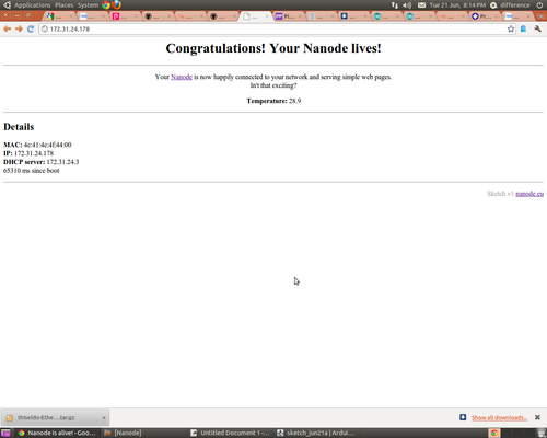
Now open a new window of your browser and point it to the IP Address as defined by My IP in the last example
My IP: 192.168.0.6
So open up http://192.168.0.6/
And your Nanode should serve its first webpage. It doesn't do much, but does have a clickable link to Andy Lindsay's blog page.
Now, edit the code and chance every reference to Arduino in these lines to Nanode
so the code looks like this:
plen=es.ES_fill_tcp_data_p(buf,plen,PSTR("<html><head><title>Nanode ENC28J60 Ethernet Shield V1.0</title></head><body>"));
plen=es.ES_fill_tcp_data_p(buf,plen,PSTR("
Welcome to Nanode ENC28J60 Ethernet Shield V1.0
")); plen=es.ES_fill_tcp_data_p(buf,plen,PSTR("-- Put your Nanode online -- "));
Now re-compile and upload and refresh your browser window - you should see the text changes you made in the code reflected in the served page.
Note:
To get the EtherShield examples to work you will have to edit the enc28j60 init function to read.
ES_enc28j60Init(mymac,8);
In the webserver example this can be found on line 48.
EtherShield simpleClient examples for Pachube and Emoncms: github
Here's someone's notes about putting the ENC28J60 into sleep mode so it doesn't use so much power.
http://blog.derouineau.fr/2011/07/putting-enc28j60-ethernet-controler-in-sleep-mode/
Simple Applications
Here's some ideas to get you started with your Nanode. Feel free to add your favourite applications to this section. Wherever possible provide a link to relevant external information, code examples or a link to a GitHub Gist which can be quickly cut and pasted into a new code sketch.
Nanode Basics
Nanode is very similar to the Arduino - in fact anything that you can do on an Arduino can be done, almost without modification, on the Nanode. The Nanode provides the familiar Arduino shield connectors - so you can plug a wide range of shield and protoboards straight into the top of the Nanode.
With a shield in place, Nanode provides a second row of connectors on each long edge of the PCB - these connectors have been tailored to suit the needs of a variety of hardware devices.
Nanode can be fitted with a row of connector pins on the top edge of the pcb, so that it can be plugged into a standard breadboard. Unlike the Arduino, all of the available I/O, both analogue and digital and power can be accessed from this single in line (SIL) connector - making connection to a breadboard simple, quick and easy.
Lighting The Red LED
Nanode comes with a version of the LED Blink program already loaded into the ATmega328 microcontroller, done along with the bootloader. When you power up your Nanode for the first time - if all is well, the red LED will begin flashing.
The LED is driven by digital pin 6 - whereas on the Arduino it is pin 13. Another difference is that the sense of the LED is inverted, you need to make the digital output pin LOW in order to bring the LED on. These changes are because the way in which Nanode handles it's local serial port - and this will be explained in a later section.
The LED was moved from 13, because pin 13 is in almost constant use by the SPI bus which talks to the ethernet controller.
Connecting a RGB LED
An RGB LED is a cheap and effective way of signalling changing environmental measurements or "moods". By fading the individual LEDs you can create a very large range of subtle colours. Using simple ramping up and down of Blue Green and Red will produce a display that could indicate temperture or power consumption starting at blue, fading through green and then through orange into red.
Use the PWM channels on digital 3, digital 5 and digital 6 to drive the red, green and blue anodes. The common cathode connects to 0V
Remember to use a current limiting resistor of at least 100 ohms in series with each LED. A ping pong ball or other semi-opaque plastic globe forms an attractive mood light. Cheap LED lamps available from Homebase for £2.50 each in a number of novelty shapes - globe, cube, heart and star.
Connecting a Radio Control Servo
Use the servo/display connector adjacent to the 5V regulator. Plug the 3 wire servo cable directly into the end three pins of the connector - noting that the red +ve supply to the servo goes on the left.
Connecting a "Modern Device" LCD serial Display Controller
Use the servo/display connector adjacent to the 5V regulator. Plug the 3 wire display cable directly into the end three pins of the connector - noting that the red +ve supply to the servo goes on the left.
Use the software serial library on digital 4 to send serial text and commands to the display.
Using Arduino Shields
You can plug Arduino shields into the Nanode provided that you consider the following points:
Nanode uses digital 8,11,12 and 13 to control the ENC28J60 ethernet controller.
Nanode uses digitals 7,9,10 to a certain extent depending on what hardware options have been fitted.
You may need to use "stackable headers" to lengthen the pins of your shield, so that it has clearance over the Magjack connector - available from Cool Components
Connecting to 1 Wire Sensors
You can connect to a variety of 1 wire devices including temperature and humidity sensors
Use the Arduino 1 wire library for example sketches
Note that Digital 2 is used for the interrupt input from the wireless module - if fitted. Please use Digital 3 for Onewire to avoid any signal conflict.
Connecting to Thermistor Temperature Sensors
Thermistors are a low cost temperature sensor available in a wide range of shapes and sizes to suit your application. For example if you wish to monitor your heating system, you might use the clip on pipe sensors from Rapid Electronics.
Thermistors are generally built into a potential divider circuit using a resistor of similar value to that of the thermistor - eg 10K for a thermistor which has a resistance of 10K at 25 degrees C. The thermistor should be put in the upper arm of the potential divider so when the temperature rises, its resistance drops and so the voltage at the mid-point of the divider rises.
This voltage is read using one of the analogue inputs, but the input has to be linearised and scaled so that it reads correctly in degrees C. Fortunately the code to do this is available on the Arduino Playground. and a more advanced example which uses the Steinhart-Hart Linearisation Equation
Using the Local Serial Bus
For some applications, several Nanodes need to be connected together as a distributed monitoring and control network and be controlled by a master device, possibly connected to the internet.
The Nanode Local Serial Bus was devised as an economical way of doing this, without having the cost and complexity of the ethernet controller and mag-jack on every board.
The local bus can use inexpensive 4 core telephone cable to distribute power and communications between each board in the network. A power supply voltage of 12V is recommended.
Each board takes its power from the bus, which can be up to 500mA maximum for standard 26 gauge telephone wire. This means that slave boards can power small electromechanical devices such as relays, motors, servos and solenoids using the bus power.
Communications over the bus is done using 5V signal levels and from testing we found that 9600 baud worked well at distances of up to 300m of cable.
The allocated Master device has ultimate control over the bus, and sends out packets of serial data to which the slaves respond, possibly returning their data to the Master.
For this to work - we need a system of bus arbitration, such that there is only one device talking on the bus at any time. In the Nanode, this bus control is done using a pair of tristate buffers, which are left over from the four in the 74HC125 device - where only two were used for the ethernet controller glue logic.
Let us assume that all slaves are listening to the bus - in otherwords their Rx pin is electrically connected to the Transmit line of the Master device via the bus. The master will address a slave by sending a packet of data which contains the (destination) address of that node. When a slave sees it's own address come up, it decodes the packet of data, which is usually a command allowing the slave to access the bus, and transmit its data back to the master.
To do this, the slave must enable it's Transmit tristate buffer by lowering digital 6. This allows the slave to send data to the bus, where the master, will receive it. By lowering pin 6, the Red LED will also be turned on, and this gives a visual indication that that slave has been selected and that it is accessing the bus. This is the reason that the LED is on pin 6.
The slave sends its data to the master and then releases the bus - by raising pin 6 and the LED will turn off.
Trystan Lea of openenergymonitor.org has written a comprehensive library to allow a master slave network to be set up. See his documentation here about Networked Arduinos
For a very similar project of a wired serial bus which uses the RS485 physical layer see Rob Gray's project. Busnet Project. This will be relevant if the Nanode is to be used as a DMX lighting controller.
Webserver Application (Dave Ingram)
Dave's code is in his Github repository
https://github.com/dingram/Nanode/
Webserver Application with Live Analogue Thermistor Served on Webpage(samthetechie and lambda25)
This code is derived from Dave's example and an arduino playground example shows a live sensor reading from Analogue 0 on the webpage upon page refresh. The trick to getting this to work was to use dtostrf() instead of sprintf() for the float to string conversion.
- Code: https://github.com/Nanode/Webserver-Live-Thermistor-Reading
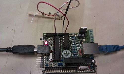
- Screenshot
- Photo
Connecting to your nanode from behind a router
So far In the above screen shot we are reaching the nanode on the local network directly with its IP address. However, the purpose of this project was to have a remote sensor that you could get to from anywhere. In this case you need to do some basic port forwarding from your external IP (that of your router usually) and the internal IP of the nanode on your local network.
If you aren't familiar with "port forwarding" it is best to google or wiki it, whilst the basic principle is the same, the exact procedure depends on your router.
The General procedure is as follows:
- Connect The nanode to power, Ethernet and the sensor board (in our case a simple thermistor circuit)
- Wait for it to get an IP (for DHCP) or just for it to connect (if you have assigned a static IP in your sketch)
- Connect to your router and find the IP address of your nanode
- Find your External IP by googling "my IP address"
- Make a Port forward from your external IP eg 45.69.124.22 choosing any port you like eg port 5000 to the nanodes IP on port 80 eg 192.168.1.12:80
And that's it, now you should be able to type your external IP and the chosen Port into your browser (eg.45.69.124.22:5000) and be directed to the webpage served by the nanode, from anywhere :D
Keep in mind that if your external IP Changes or your router assigns a new IP to the Nanode (as happens with DHCP), you won't be able to reach it. That is why it is best to set up a static IP in both cases if you intend on having a more permanent set up. If you don't have a static external IP, you can use a dynamic DNS service such as DynDns.com or No-IP to get a fixed hostname (e.g. myhome.dyndns.com) that always redirects to your external IP address.
USB Bootstrap loader
The template for the USB boot loader is USBaspLoader. It needs to be built using these config files.
There are some caveats. Read the notes.
MAC address
The code for reading the unique MAC Address is now available.
threebytesfull has been working hard on this on Sat June 11th - and reports that he can now read the MAC chip - well done. Code for reading this device - see Github for MAC reader
Once you have successfully read your MAC address, you can enter it next to your Nanode serial number in The Complete List.
If you did not have your tiny MAC chip soldered to the back of the pcb during the Nanode Weekend - this can be done at a later date at the space. Ken next available to do this at London Hackspace on evening of 14th June.
RFM12 Wireless Module
Wireless connectivity can be added to the Nanode using the Jeelabs RFM12B wireless board. Schematic can be viewed here. No need to solder in the 3.3V regulator or capacitors the board will gets it's 3.3V power from the Nanode.
For compatibility with the emonTx from OpenEnegyMonitor.org ensure the 433Mhz RFM12B module is used (this frequency can be used worldwide). JeeLabs use 868Mhz which can only be used in Europe.
RFM12B modules can be bought in the UK from RS, Rapid or Farnell.
The JeeLabs RFM12B board plugs into a special port on top the Nanode. This port is different to the Arduino header just below it. An extra 8 pin female header will need to be soldered in. See image below:
Update 24/10/11 by Glyn Hudson ([openenergymonitor.org]):
There is an error on the Nanode 5 board layout. That stops the Ethernet and RFM12B being used at the same time. See below for explanation and solution:
Explanation:
The INT/IRQ signal from the RFM12B socket is mistakenly OR'ed with the INT from the ENC28J60 Ethernet Chip before going into the 74125 Tri-state buffer which acts as a 3.3-5V level converter.
If the ENC28J60 sets its interrupt line high, then the low going RFM12 interrupts will be pulled up by this high signal so they might only get down to 1.5V which is too high to register as a logic 0. The 10K resistor R13 also pulls the INT line high. This stops the RFM12B working at the same time as the ENC28J60.
Solution:
The solution is to lift pin 4 of the ENC28J60 out of its socket and not solder in/remove R13 (the 10K resistor, one resistor down from the 1 ohm ferrite). This disconnects the ENC28J60's INT line (which is not used) from the circuit and removes the resistor which was pulling the line high.
No additional wire link is needed as first though.
RFM12 example with DHCP and DNS and posting data via Ethernet to Pachube and emoncms by OpenEnergyMonitor: download from github
Bitlash
Bitlash is a interpreted command shell (language) which runs on the Arduino. It takes 14K of program memory, but allows programs to be written from a serial terminal and stored as functions in the EEprom on the ATmega328. It is reminiscent of the early 1980s home computers which executed BASIC directly from power-up.
Bitlash could be used to write simple scripts to automate sensing functions, datalogging or other applications running on Nanode. There is an opportunity to be able to reprogram a Nanode remotely, and have it perfor different tasks.
Bitlash can incorporate any of the Arduino library functions, making it simple to combine Bitlash with existing C-code.
More infomation here Bitlash Wikki
SPI Serial SRAM
On the underside of the Nanode 5 pcb is a footprint to accept a SPI memory deviice. This can be EEprom, data flash, SRAM or FRAM (ferroelectric memory).
I have done some test code for the very cheap (£1.20) 23K256 spi SRAM which is a 32K byte device.
You can find my test code on the following Github Gist
https://gist.github.com/1020771
There is also an Arduino library to support this device - find it here
If you intend to run the SPI SRAM, you will need to modify the way the board is powered - so that everything runs off 3.3V. See below for details.
Running the board on just 3V3
Nanode 5 uses both 5V and 3V3 to run the on-board devices. This has been done mainly as a convenience so that it is compatible with Arduino and Arduino shields which generally use 5V.
However, there are an increasing amount of low power devices which only need 3V3, such as the on board ENC28J60 ethernet controller and the spi memory device on the underside of the pcb - so advanced users may wish to modify their boards to run solely on 3V3 - particularly if they are to access the spi SRAM.
First you have to identify where 5V is produced or enters the pcb. Either the red wire of the FTDI cable, the USB jack or the 5V 7805 regulator. Having identified these sources you need to isolate them or in the case of the regulator modify so that they produce 3V3.
One way would be to remove the existing 5V 7805 regulator and replace it with a 3V3 regulator, and then cut the pin on the FTDI connector that feeds 5V to the pcb and wire a link from this severed pin to the new input of the newly added 3V3 regulator. For completeness you would also need to cut the 5V input track that comes from the USB socket.
Once you are feeding the 5V into the new 3V3 regulator, you need to connect this 3V3 to the existing 5V rail. The easiest way is a wire link which connects pins 2 and 3 of the Arduino shield "power" connector.
A pictorial guide to this modification will be provided later.
RESTduino
RESTduino provides a way to directly control the Nanode hardware from a client - server session. The commands that you want to run on the Nanode are encoded into the URL. For example turn I/O pins on and off or read an analogue temperature sensor.
We hope to combine RESTduino with the bitlash command interpreter to make an interactive way of running scripts on Nanode and editing them remotely.
Here's what Andy Lindsay says about RESTduino and how to run it on your Nanode.
EtherShield RESTduino
- IMPORTANT NOTE **
This version of RESTduino is for ENC28J60 based ethernet shields only, not the Official Arduino Ethernet Shield, these use the wizznet chips, it is very heavily based on the original RESTduino by Jason Gullickson, full details at: http://jasongullickson.posterous.com/restduino-arduino-hacking-for-the-rest-of-us. Full thanks and credit go to Jason for the original code and ideas. I have taken his work and massaged it into an application that works with the ENC28J60 based ethernet shields.
I've also updated the demo to use 3 sliders to change the colours on a RGB LED.
This should also be compatible with the Nanode boards described at http://nanode.eu
RESTduino is a simple sketch to provide a REST-like interface to the Arduino via the Ethernet Shield. The idea is to allow developers familiar with interacting with REST services with a way to control physical devices using the Arduino (without having to write any Arduino code).
Of course some flexibility is traded for this convenience; only basic operations are currently supported:
- Digital pin I/O (HIGH, LOW and PWM)
- Analog pin input
Later versions of the sketch may provide additional functionality (servo control, etc.) however if you need more than just basic pin control you're probably better off learning the basics of programming the Arduino and offloading some of your processing to the board itself.
Getting Started
First you'll need an Arduino, a ENC28J60-based Ethernet shield and the Arduino development tools; here's some links to get you started:
- Arduino Uno (adafruit): http://www.adafruit.com/index.php?main_page=product_info&cPath=17&products_id=50
- EtherShield (nuelectronics): http://www.nuelectronics.com/estore/index.php?main_page=product_info&products_id=4
- Arduino development tools: http://www.arduino.cc/en/Main/Software
Or you could use the Nanode, http://nanode.eu which combines both the Arduino functionality and the EtherShield on one board. If you use a Nanode then you will additionally need the FTDI programming lead.
For testing you'll want some hardware to connect to the Arduino, the demo uses a common cathode RGB LED connected to pins 3, 5 and 6. Connecting single LEDs between the pins and ground will also work.
Load up the sketch (EtherShield_RESTduino.pde) and modify the following lines to match your setup:
static uint8_t mymac[6] = { 0x54,0x55,0x58,0x10,0x20,0x35};
This line sets the MAC address of your ethernet board;
static uint8_t myip[4] = { 192,168,1,177};
The next line you'll need to modify is this one which sets the IP address; set it to something valid for your network.
Now you should be ready to upload the code to your Arduino. Once the upload is complete you can open the "Serial Monitor" to get some debug info from the sketch.
Now you're ready to start talking REST to your Arduino/Nanode!
To turn on the LED attached to pin #3 (currently case sensitive!):
This will set the pin to the HIGH state and the LED should light. Next try this:
This will use PWM to illuminate the LED at around 50% brightness (valid PWM values are 0-255).
Now if we connect a switch to pin #2 we can read the digital (on/off) value using this URL:
This returns a tiny chunk of JSON containing the pin requested and its current value:
{"2":"LOW"}
Analog reads are similar; reading the value of Analog pin #1 looks like this:
...and return the same JSON formatted result as above:
{"a1":"432"}
Javascript/jQuery Demo
A simple example of how to interface with RESTduino via jQuery is included as DemoApp2.html.
This page displays 3 slider controls (via jQuery UI) which when adjusted will set the PWM value of Pin #3, #5 and #6 to the value selected by the slider. These then change the appropriate colour on the RGB LED.
If you look at line 32 you can see where the REST URL (you'll need to adjust this for the IP address of your device) is constructed based on the selected value of the slider and on lines 53, 63 and 73 an AJAX request is executed passing the URL constructed above to the Arduino.
Combining Bitlash and RESTduino to make a simple Scriptable Device
Bitlash is a simple interpreted script language which runs on Nanode or Arduino. It allows you to define new functions, store them to EEprom memory and to control the I/O port pins with a few simple commands typed over the serial port. It's a little reminiscent of the late 70's early 80's home-computers that from power-up ran an interpreted basic. It's better than basic because it ties in with the Arduino libraries ad function calls, and you can mix your C code with Bitlash running in the background - it just seems such a cool idea as an interface to a simple microcontroller.
Bitlash has a Telnet example, so that you can Telnet into it remotely and edit scripts to control different things. Well you could - if our TCP/IP stack supported a Telnet Client. Unfortunately it doesn't, so we have to find another way of getting our command line data up to the Nanode.
One neat way of doing this is to embed the command line at the end of the URL you send to your Nanode server, and then persuade the Nanode to send you something useful back.
Suppose your Nanode is at IP Address 192.168.0.105 and has the means to serve a simple web page assembled from HTML and text in a small text buffer. Lets call this page page_one
HTTP allows for subfolders, so if your page was in a subfolder called password, you could type
http://192.168.0.105/password/page_one and it would serve the page.
If however you don't spell password correctly, the device will return with a 404 error - page not found. This simple mechanisms allows very crude password control over what is served - important if you don't want everyone tinkering with your Nanodes.
I've been looking at the RESTduino example - and it is quite simple to see how the code parses through the URL looking for backslashes and stripping out the parameters contained between them.
The command buffer is set to 50 characters - but I am sure we could extend this to get a good line length - say 127 chars.
So a merge between REST and bitlash would just have to have the REST command line buffer deposited into the bitlash command line buffer (make them one and the same) and bitlash will execute the commands included in the URL.
There is then another string buffer called the Client line - and this is used to send text back to the client. Again bitlash would populate this with the output response from the executed command and send it back.
So let's assume there's a Nanode lurking at IP Address 192.168.0.105
Bitlash sends its ">" prompt to the Client line
The user then wants to get the Nanode to print the answer to the sum 2 + 2 so the User types into the URL window of their browser
http://192.168.0.105/bl/PRINT 2+2 <CR>
The REST code, parses the URL from its command buffer until it finds the first backslash after the IP address where it encounters /bl and so it knows what next is going to be a bitlash command rather than a REST command
/bl/PRINT 2+2 <CR>
it then takes the PRINT 2+2 up to the final <CR> and puts that into the Bitlash command input
Bitlash parses and executes this command and prints 4 back into the Client's Line, followed by a newline and its > prompt.
To make this nice and elegant we would just need a bit of processing code or Python, which accepts lines of text commands and precedes them with the http://192.168.0.105/bl/ header.
IPV6 and uIP
uIP is an alternative TCP/IP stack written for resource limited microcontrollers.
Guenther Hoelzl has combined uIP plus the ENC28J60 library from Guido Socher, to make an IPV6 implementation - which will run on any arduino like device with ENC28J60 ethernet controller - including Nanode of course.
http://sites.google.com/site/ghoelzl/ipv6ethershield/ipv6_telnet_server
1st August - Stephen Early @sde1000 reports that he has successfully ported uIP to his Nanode and it responds to pings and DHCP now working! - Good work Stephen - we look forward to further developments along these lines.
Jee Labs EtherCard Library
The Jee Labs EtherCard Library works on Nanode with no modifications whatsoever. It even uses pin 8 for SPI chip select. Examples and details on maniacbug's blog.
Now re-compile and upload and refresh your browser window - you should see the text changes you made in the code reflected in the served page.
Note:
Here's someone's notes about putting the ENC28J60 into sleep mode so it doesn't use so much power.


Update 24/10/11 by Glyn Hudson ([openenergymonitor.org]):
Explanation:
Solution:

No additional wire link is needed as first though.
EtherShield RESTduino
- IMPORTANT NOTE **
Of course some flexibility is traded for this convenience; only basic operations are currently supported:
1st August - Stephen Early @sde1000 reports that he has successfully ported uIP to his Nanode and it responds to pings and DHCP now working! - Good work Stephen - we look forward to further developments along these lines.