Difference between revisions of "Project:SpeedAdjustableBikeLight"
m |
|||
| Line 1: | Line 1: | ||
__NOTOC__ | __NOTOC__ | ||
=LED lights and lenses for my bike= | =LED lights and lenses for my bike= | ||
| + | |||
| + | ==Pending stuff== | ||
| + | Last minute board layout!! | ||
| + | |||
| + | How to link board to wires. After lots of thinking I have decided to use screw terminals, what digikey calls "terminal blocks - wire to board". | ||
| + | |||
| + | Major benefit is that these terminals can have same spacing as old 0.1 inch DIPs and | ||
| + | breakaway headers and hence no-solder boards! And they are more dense than the hand soldering loose wires would be (given my skill levels). | ||
| + | 1x [http://www.digikey.co.uk/product-detail/en/282834-4/A98335-ND/1153265 four-way] £ 1.18 | ||
| + | 2x [http://www.digikey.co.uk/product-detail/en/282834-2/A98333-ND/1150135 two-way] £ 0.76 | ||
| + | |||
| + | So can use 0.1 breakaways in board design - just need to leave a bigger box for the screw terminal later. box dimension is 6.5mm by (pins * 2.54 + 0.5) mm. | ||
| + | |||
| + | If I want to use pins in solder free boards need to lay out on 0.1 grid, and make sure the pins will work with the bus that these boards define, seems like a bit of work... more thinking reqd. | ||
==Overview== | ==Overview== | ||
Revision as of 14:44, 6 May 2012
LED lights and lenses for my bike
Pending stuff
Last minute board layout!!
How to link board to wires. After lots of thinking I have decided to use screw terminals, what digikey calls "terminal blocks - wire to board".
Major benefit is that these terminals can have same spacing as old 0.1 inch DIPs and breakaway headers and hence no-solder boards! And they are more dense than the hand soldering loose wires would be (given my skill levels). 1x four-way £ 1.18 2x two-way £ 0.76
So can use 0.1 breakaways in board design - just need to leave a bigger box for the screw terminal later. box dimension is 6.5mm by (pins * 2.54 + 0.5) mm.
If I want to use pins in solder free boards need to lay out on 0.1 grid, and make sure the pins will work with the bus that these boards define, seems like a bit of work... more thinking reqd.
Overview
My motivation is to have fun while learning about designing PCBs, and using microcontrollers, MOSFETs and LEDs - with a simple objective to measure my progress against.
I came across this page that explains the benefits of matching LEDs to bike generators.
Since LEDs seem cheap and the available energy is small, I refined the plan. Build several strings of LEDs with different beam angles and aiming points - and the choose the string of LEDs to turn on for the current bike speed and conditions.
Initial target:
- generate some difuse light at low speed
- generate more focussed light at high speed
- make it work
- dont break the bank
Advanced target:
- during the day, flash the LEDs to attract attention.
In progress lessons
- how to use Farnell component search
- how to use Digi-key component search
- how to use Eagle CAD:
- to make components
- to enter schematic
- to layout a board
Physical progress
- purchased LEDs, reflectors and lenses from ebay.
- scrounged an attiny85 from the space components.
- scrounged a bottle dynamo from Walthamstow bike recycling centre.
- drilled and milled the LED lense mounts.
- purchased parts from DigiKey
- LT3008ETS8-2.5#TRMPBFCT-ND | 1 | 2.19 | 2.5V Voltage regulator
- DFLS130LDICT-ND | 7 | 0.252 | 30V | 1A Schottky Diode
- 568-7420-1-ND | 4 | 0.32 | MOSFET N-CH 30V 4.9A 6TSOP
- MMSZ4680T1GOSCT-ND | 1 | 0.19 | DIODE ZENER 2.2V 500MW SOD-123
- SMBJ5361B-TPMSCT-ND | 2 | 0.63 | DIODE ZENER 5W 27V SMB
- 445-1386-1-ND | 1 0.17 | CAP CER 4.7UF 10V 10% X5R 1206
- PDV-P5001-ND 1 | 1.3 | PHOTOCELL 8K-16K OHM 11MM
- 311-10.0KFRCT-ND | 10 | 0.01 | RES 10.0K OHM 1/4W 1% 1206 SMD
- 311-825FRCT-ND | 1 | 0.02 | RES 825 OHM 1/4W 1% 1206 SMD
- made schema
- two board layouts, I havnt worked out how to print them yet.
Thinking progress
- examined MOSFETs, Voltage regs and Diodes from Farnell - built a partslist for Max 20V parts.
- rough circuit plan
- rough firmware plan
- found a better regulator in digikey and am re-examining the parts list.
Open questions
- How to mount and cool the LEDs?
- on a horizontal copper heat pipe
- How to mount the circuit board?
- What is the maximum voltage to plan for?
- 28V
LED behaviour
The LEDs are Luxeon StarIII (white Lambertian .
At 0.7A and 25deg junction temp, voltage per LED varies between 3.03(min), 3.7(typ), 4.47(max). And 3.9V(typ) at 1A current.
Some uncertaintity - current might just get to 0.5 A but I am sure the junction will be hotter than 25C, and see but no indication of change in V drop with temp in the datasheet :(.
I tested one LED, and it turned on at 3.2V and was easy to overdrive using the Maplin adjustable current bench supply. I wont do that again:(. It still works, but I guess 3 seconds of 2A current in a 1A LED is bad for it.
Lense behaviour
I bought 4x30deg, 3x15deg and 3x5deg reflecters.
I tried the 5 degree lense over the LED, but the wires on the LED pushed the mount away from the led - leaving a ring of light on the wall surrounding a central dark spot.
The second attempt involved melting the bottom of the mount to allow space for the wires.. the ring is smaller but still has a dark spot in the centre :(.
Holding the lense over the LED I got a bright spot on the wall:).
I will need to carfully cut slots in the mounting for the wires.
thinking space
Original plan is for four LED strings
- - very low speed - just a 120 deg med power LED (with voltage doubler to get the reqd V)
- - low speed - one 30deg
- - med speed - one 30deg, one 15deg
- - high speed - one 15deg, two 5deg
Of course, the length of the strings depend on the V generated by my bike speed.. so not really predictable
Simplify (only last 3 strings) and no V doubler.
This just fits in the attiny85 pinout - but the attiny84 has more scope and flexibility.
New link on impedance matching and MCU control of bike lights :). I am not sure what this means for my circuit and plans.
Now using attiny84 - added
- fourth mosfet (for another LED string)
- voltage sense (to control pulsing of LED strings when there is insufficient power)
- light sensor
- JTAG debugging
- Chip Select for possible communications via SPI.
Another consideration is that SPI or TWI might be enough to to talk to other devices e.g. USB, ZigBEE, GPS or whatever. And the SPI/TWI pins are all on the clasic JTAG header, which is a luxury the attiny85 can not support.
Ongoing...
- How to do solder stencil? On laser cutter..
- How to do solder prep? Sqeegee..
- Soldering? Frying pan..
- Validate the schematic and board?
- Have the boards made..
Plan to make a heat pipe and sink combo. Starting with a copper tube long enough to mount across the handle bars. Flatten spots in the tube to mate with the LED aluminium carrier boards at angles that get the LED light pointed on the road, not in drivers eyes. Add water and heat it up so it boils, and seal it while filled with steam. The steam will condense to form a partial vacumn. Sounds so simple!
Start software development... the easy bit.
Switches for LED current
- This PNM34UN is 2A mosfet, with Rds of 0.08 at 1.8V throu to about 0.05 at 4.5V; max Vds of 30V; £0.16 each. there are several similar parts at Vds 30V for a bit more money. digikey is more expensive for this part.
Voltage regulator for the MCU
Needs to operate of a widely varied supply voltage. The dynamo generates a voltage proportional to the bike speed. Potentially reaching hundreds of volts. And the higher the voltage climbs, the more power I can use in the LEDs! Many components to deal with 0.5A are specced at about 40 to 60V - so that is a very high limit for the working voltage. A chain of 6 LEDs would need 24v. My plans are for 3 LEDs in a chain - so 20V is a good target.
- LT3008 2.5V fixed from Digi-Key. Is easier to check for alignment on board. Doesn't need the resister network. And is cheaper.
Diodes for rectifying AC
This diode should allow be low voltage drop - to get the LEDs working at lower speeds. Need to be >10V barrier. Higher barrier gives higher drops. So chosen 15V barrier diode.
- digikey 1A 30V 0.31 voltage drop £0.38/1 £3/10
light sensor
All the Farnell photo-resistors are through hole; makes sense I guess as that way they can be poked through a hole in the casing.
- photo-resistor or LDR is cheapest at £0.27 - now to find out how to use it, and if there is a reason to spend more.
20V, 30V or 60V diode bridge.
Since the voltage out of the dynamo is essentially a function of the road speed, it could be quite high.
A pair of zener diodes across the output of the dynamo - before the rectifier can discard the extra power.
Two 5W 27V zeners will each conduct when the voltage exceeds 27V + Vf of the other diode (1.1V maybe).
MCU programming
All AVR MCUs come with debugWire disabled :( - see Connecting to a board with JTAG MK2.
To enable debugWire I need to use ISP/ which needs MISO,MOSI,SCK and RESET, VCC, and GND! Can do with the DIP by programming before putting in the board; using a socket.
I wonder how the users of SMD packages manage it?
I have copped out and am setting up JTAG :).
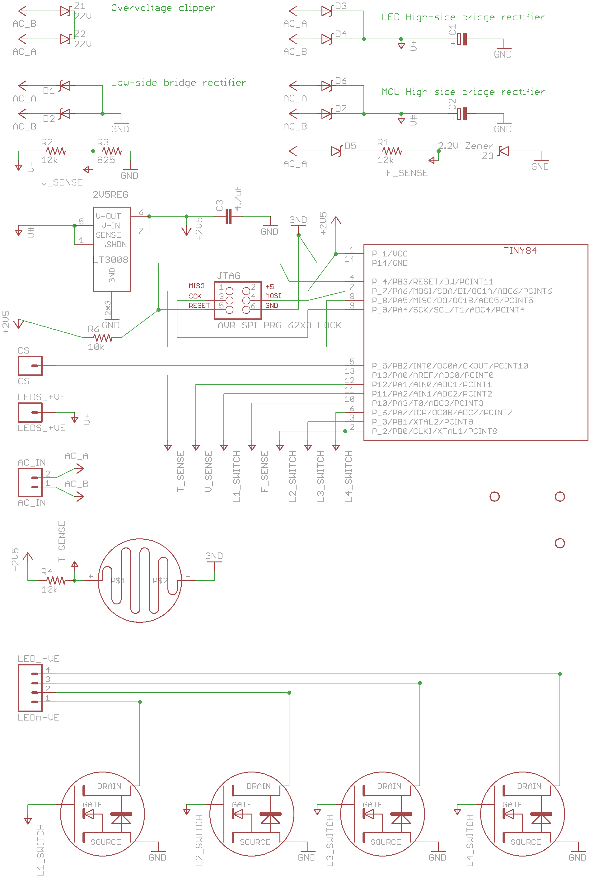
circuit design
(see actual schema)
- dynamo->AC
- AC -> back-to-back 5W 27V zener diodes -> clipped AC. //Clip the AC to ~29V
- Three pairs of 30V schottky diodes rectify into:
- GND //or low side
- V+ //high side for LED power
- V# //high side for voltage regulator
- V+ -> 10k resistor -> MCU_[ADC] -> 825 resistor -> GND // so the code can monitor power usage
- (four of) V+->LED strings->logic level 30V mosfets->GND // actual power usage
- V# -> 2.5V reg -> V2p5 -> MCU -> GND // MCU power
- AC -> diode -> 10k resister -> MCU[T0] ->2.5V zener diode -> GND // AC frequency counter, i.e. bike speed sensor
- MCU_reset -> JTAG -> 10k resistor -> V2p5 // Reset pullup
- MCU_[3*gpios] -> MOSFET Gates // control of power usage
- V2p5 -> LightDependentResistor -> MCU_[ADC] -> 10k resistor -> GND // Light sensor, is it dark out?
- MCU_[Vcc, GND, Reset, MOSI, MISO, SCK] -> JTAG circuits // MCU programming, other stuff maybe
- MCU_[spare pin] -> CS // for SPI stuff, other stuff maybe
I dropped these circuits as the voltage clipping diodes can eat 10W, so the MCU should have time to start control before overpower is a problem; and a lockup in the MCU **could** override the hardware anyway.
- DC->1M resister->MOSFET_on->2.7V zener diode->GND (hardware default this MOSFET to on)
- MOSFET_off(two off)->1M resistor->GND (hardware default these MOSFETs to off)
firmware design
pseudo code
isr(int0)
 {
 freq++ ;
 }

isr(counter_2_overflow)
 {
 // copy current freq to main line, reset freq.
 }

isr(adc_complete)
 {
 copy adc value to mainline;
 }

isr(counter1_...)
 {
 // implement the lighting policy
 ?flip the current MOSFETs bit..
 ?change the current MOSFET
 ?change the counter target
 }

void
main()
 {
 setup() ; // set the ports, direction etc.
 for(;;)
  {
  if (newFreq)
   {
    {
    DISABLE_ISR ;
    copy new freq ;
    }
   if new freq != old freq
    adjust policy;
   }
  if (newLumons)
   {
    {
    DISABLE_ISR;
    copy new lumons;
    }
   if new lumons != old lumons
    adjust policy ;
   }
  }
 }
inputs and conditioning
policy ideas
- if it is dark provide constant light immediately.
- if it becomes light, wait for a few seconds to confim it stays light, and then start flashing the lights to make it easier for others to see the bike.
- as the speed increases, spend more time with tightly focussed lights lit
- as the speed decreases, spend more time with flood lights lit.
- Flashing LEDs use less power, maybe can lit up high speed strings at lower speeds?
- Flashing LEDs have higher power limits, so should be able to flash low speed floods even at high speed - to get attention from road users at large angles to the bikes direction of travel.
- Aim to match the power available to the power consumed by the LED strings
policy mechanism
Four intervals of variable length, applied to selected string of LEDs: off, string-a on, off, string-b on.
The intervals are defined as an array of counter[4]. The LED strings by the MOSFET number in an array of mosfet[4];
This will allow:
- the fading from spots to floods gradually:).
- day lashing patterns to be set using any two strings of LEDs.
policy config
- night vs day lumonosity value.
- samples of day light required for flashing to start.
- freq exponential smoothing factor (power of 2)
- night freq bounds[4] between {floods | mix | medium | mix | spots}
- day freq bounds[N] between flash patterns
- day flash patterns[N]
user config
policy values in miles per hour? or are they automated from load/power info?