Equipment/Piccadilly circus LED sign: Difference between revisions
No edit summary |
No edit summary |
||
| Line 41: | Line 41: | ||
[[File:TB2706-sipo.png]] | [[File:TB2706-sipo.png]] | ||
Note: The arrangement of the pixels is not a nice linear buffer! I will put this up shortly... | |||
== Writing stuff! == | == Writing stuff! == | ||
| Line 54: | Line 56: | ||
RGB gradients are accomplished by writing the data fast enough to do PWM. | RGB gradients are accomplished by writing the data fast enough to do PWM. | ||
== Things done with the tile so far == | |||
[[File:Led-h.jpg]] | |||
Revision as of 00:36, 19 January 2012
The LED sign is awesome in every way the jumbotron was not: it has high pixel density, brightness, and low weight, AND pretty simple insides.
This Howto is a basic hack to drive on of the tiles
What is what
The board is made of segments each with four columns and a column has three tiles. Each tile has 16x16 pixels RGB.
In this document we are interested in the tiles as they are the easiest. They can be driven my AVR/Arduinos
Instructional video by Mike Harrison
Pinout
The tiles have the following pinout
 1. FLACK
 2. NC
 3. NC
 4. MA0
 5. MA1
 6. NC
 7. NC
 8. NC
 9. R_EN
10. G_EN
11. B_EN
12. GND
13. R_DATA
14. GND
15. G_DATA
16. GND
17. B_DATA
18. GND
19. SCLK
20. GND
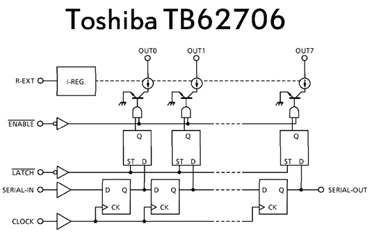
Inside the module looks like this
Note: The arrangement of the pixels is not a nice linear buffer! I will put this up shortly...
Writing stuff!
Hook all the pins up and strobe them all high. Basically the FLATCH signals the start of the frame. The R_EN, G_EN, B_EN need to be pulsed high at the start if you want those colours.
Then drop them all low. Now write one bit by placing the data on R_DATA, B_DATA and G_DATA pins with CLOCK high. Then drop the CLOCK. Data is written on the falling edge.
How should it work?
Well this is a hack. Please read the documentation for proper timing diagrams. It is supposed to be driven at 12.5mhz but anything lower shouldn't spook it too much and an ardiuno/avr is not going to get close to that clock frequency.
RGB gradients are accomplished by writing the data fast enough to do PWM.

