Project:HM55B: Difference between revisions
mNo edit summary |
|||
| (43 intermediate revisions by 7 users not shown) | |||
| Line 1: | Line 1: | ||
== | == About the module == | ||
$20-25 compass module for embedded systems. | $20-25 compass module for embedded systems, this comes in a convenient DIL package. | ||
The SMD will probably be cheaper, though I have not managed to source one yet. | |||
[http://www.parallax.com/dl/docs/prod/compshop/HM55BModDocs.pdf Datasheet] | [http://www.parallax.com/dl/docs/prod/compshop/HM55BModDocs.pdf Datasheet] | ||
Italics in this article are straight quotes from datasheet. | |||
== Bus Pirate pinout == | |||
From http://dangerousprototypes.com/docs/Bus_Pirate_101_tutorial | |||
<pre> | |||
Pin name Description (Bus Pirate is the master) | |||
MOSI Master data out, slave in (SPI, JTAG), Serial data (1-Wire, I2C, KB), TX* (UART) | |||
CLK Clock signal (I2C, SPI, JTAG, KB) | |||
MISO Master data in, slave out (SPI, JTAG) RX (UART) | |||
CS* Chip select (SPI), TMS (JTAG) | |||
AUX Auxiliary IO, frequency probe, pulse-width modulator | |||
ADC Voltage measurement probe (max 6volts) | |||
Vpu Voltage input for on-board pull-up resistors (0-5volts). | |||
+3.3v +3.3volt switchable power supply | |||
+5.0v +5volt switchable power supply | |||
GND Ground, connect to ground of test circuit | |||
</pre> | |||
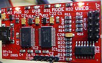
[[File:Buspirate.jpg|200px]] | |||
In the photo the pins on right connector, from top left: | |||
GND +3.3V | |||
+5V ADC | |||
Vpu AUX | |||
CLK MOSI | |||
CS MISO | |||
== Connecting == | |||
=== Wiring === | |||
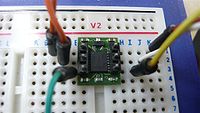
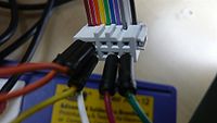
<pre> | |||
HM55B Bus Pirate | |||
Din(1) MOSI | |||
Dout(2) MISO | |||
VSS(3) GND | |||
CLK(4) CLK | |||
/EN(5) CS | |||
Vdd(6) +5V | |||
</pre> | |||
[[File:HM55B.jpg|200px]] | |||
[[File:BusPirateConnector.jpg|200px]] | |||
=== Starting a terminal session === | |||
Plug in the bus pirate then (assuming it's the only USB device plugged in a debian based os): | |||
<pre> | |||
$ screen /dev/ttyUSB0 115200 | |||
</pre> | |||
== Testing with the BusPirate == | |||
Once in the terminal session, apply these settings: | |||
* '''M''' (mode) | |||
* '''8''' (3-wire raw) | |||
* '''4''' (400KHz) | |||
* '''2''' (3.3V high) | |||
* '''W''' (turn on 5V output) | |||
NB The numbering might be different depending on firmware version. | |||
=== Checkpoint === | |||
There should now be +5v measured between HM55B pins 3 and 6. | |||
=== Abridged menu options === | |||
To cover this use case: | |||
<pre> | |||
? help | |||
/\ Clock H/L ~ CLK pin | |||
-/_ Data H/L ~ MOSI pin | |||
! Read bit ~ MISO pin | |||
[] CS L/H ~ CS pin | |||
&/% Delay us/ms | |||
: Repeat | |||
</pre> | |||
=== Reset HM55B=== | |||
Reading in plain english, "Set clock pin to low, set CS pin to low, shift out %0000 on the rising edge of the clock then set CS pin to high". | |||
Noting that CS maps to active low /EN pin. | |||
\[/_\/_\/_\/_\] | |||
Bus Pirate output - noting output formatting is configurable(TODO check options): | |||
<pre> | |||
CLOCK, 0 | |||
CS ENABLED | |||
CLOCK, 1 | |||
DATA OUTPUT, 0 | |||
CLOCK, 0 | |||
CLOCK, 1 | |||
DATA OUTPUT, 0 | |||
CLOCK, 0 | |||
CLOCK, 1 | |||
DATA OUTPUT, 0 | |||
CLOCK, 0 | |||
CLOCK, 1 | |||
DATA OUTPUT, 0 | |||
CLOCK, 0 | |||
CS DISABLED | |||
</pre> | |||
=== Start measurement === | |||
''Start a measurement by taking /EN low again, then shift-out %1000. Leave /EN low until checking the measurement status.'' | |||
[/-\/_\/_\/_\ | |||
Bus Pirate output: | |||
<pre> | |||
CLOCK, 0 | |||
CS ENABLED | |||
CLOCK, 1 | |||
DATA OUTPUT, 1 | |||
CLOCK, 0 | |||
CLOCK, 1 | |||
DATA OUTPUT, 0 | |||
CLOCK, 0 | |||
CLOCK, 1 | |||
DATA OUTPUT, 0 | |||
CLOCK, 0 | |||
CLOCK, 1 | |||
DATA OUTPUT, 0 | |||
CLOCK, 0 | |||
</pre> | |||
=== Checking measurement status === | |||
''To check the measurement status, start by sending a positive pulse to /EN. Then, shift-out %1100.'' | |||
][/-\/-\/_\/_\ | |||
Bus Pirate output: | |||
<pre> | |||
CS DISABLED | |||
CS ENABLED | |||
CLOCK, 1 | |||
DATA OUTPUT, 1 | |||
CLOCK, 0 | |||
CLOCK, 1 | |||
DATA OUTPUT, 1 | |||
CLOCK, 0 | |||
CLOCK, 1 | |||
DATA OUTPUT, 0 | |||
CLOCK, 0 | |||
CLOCK, 1 | |||
DATA OUTPUT, 0 | |||
CLOCK, 0 | |||
</pre> | |||
=== Polling === | |||
''Shift in the status flag, upon receipt of %1100, discontinue polling.'' | |||
!!!! | |||
Bus Pirate output: | |||
<pre> | |||
READ BIT: 1 | |||
READ BIT: 1 | |||
READ BIT: 0 | |||
READ BIT: 0 | |||
</pre> | |||
=== Take sample === | |||
''Leave /EN low, and move on to shifting-in the x and y-axis values.'' | |||
''Shifting-in the x and y-axis values is a simple matter of shifting-in 11 bits for the x-axis measurement followed by 11 more bits for the y-axis measurement. After completing the y-axis shift-in, set the /EN pin high again.'' | |||
!!!!!!!!!!!!!!!!!!!!!!] | |||
Bus Pirate output: | |||
<pre> | |||
READ BIT: 1 | |||
READ BIT: 1 | |||
READ BIT: 1 | |||
READ BIT: 1 | |||
READ BIT: 1 | |||
READ BIT: 1 | |||
READ BIT: 0 | |||
READ BIT: 1 | |||
READ BIT: 1 | |||
READ BIT: 0 | |||
READ BIT: 1 | |||
READ BIT: 1 | |||
READ BIT: 1 | |||
READ BIT: 1 | |||
READ BIT: 1 | |||
READ BIT: 1 | |||
READ BIT: 1 | |||
READ BIT: 0 | |||
READ BIT: 1 | |||
READ BIT: 1 | |||
READ BIT: 1 | |||
READ BIT: 1 | |||
CS DISABLED | |||
</pre> | |||
=== Sample readings === | |||
0,-6 | 0,-6 | ||
| Line 79: | Line 232: | ||
-1,-19 | -1,-19 | ||
=== Converting the reading to an angle === | |||
''The x-axis reports (field strength) × cos(θ), and the y-axis reports the (field strength) × sin(θ). To resolve θ into a clockwise angle from north, use arctan(-y/x)'' | |||
angle θ = arctan(-y/x) | |||
In the example: | |||
<pre> | |||
x = 0b11111101101 | |||
y = 0b11111101111 | |||
</pre> | |||
''The Hitachi HM55B chip on the Compass Module reports its x and y axis measurements in terms of microteslas (μT) in 11-bit signed values.'' | |||
Since both most significant bits equal one, x and y are negative and we take the two's complement: | |||
<pre> | |||
11111101101 | |||
00000010010 | |||
00000010011 | |||
</pre> | |||
x = -19 | |||
<pre> | |||
11111101111 | |||
00000010000 | |||
00000010001 | |||
</pre> | |||
y = -17 | |||
angle θ = arctan(17/-19) | |||
angle θ = -41.82 | |||
The range is plus and minus 180. Positive values sweeping east, negative sweeping west. The reading above indicates north west. | |||
=== Combining all commands === | |||
A delay is required between starting the measurement and shifting in the status flag: | |||
\[/_\/_\/_\/_\][/-\/_\/_\/_\][/-\/-\/_\/_\&&&&&&&&!!!!!!!!!!!!!!!!!!!!!!!!!!] | |||
Note that &&&&&&&& works but &:8 does not, even though the nominal value in both cases is the same, presumably because BusPirate parser adds a huge delay. This means that we don't know how fast this module can be clocked, because each ! will be > 50ms apart. | |||
The minimum required delay was 6us, 7us and 8us in three modules tested so, in production, as per data sheet, it would be a question of starting a measurement and polling status flag till 0b1100 was received. | |||
The [http://dangerousprototypes.com/docs/SPI BusPirate wiki] suggests this will work (since we've determined that it still provides the 22 sample bits even if the reading is incomplete): | |||
\[0b0000 &][0b1000 && ]&[& 0b1100 r:4] | |||
=== Exiting === | |||
ctrl-a \y | |||
== Improvements == | |||
* <s>Script all of the commands above.</s> | |||
* <s>Script to include a conversion algorithm returning an actual reading in degrees.</s> | |||
* <s>Add a compass calibration procedure (vital), though the proof of concept works so might not be practical to do this at the bit level.</s> | |||
== Source code == | |||
All improvements implemented in C. | |||
Code: [https://github.com/dsikar/at90usb162_HM55B github.com]. | |||
[[Category:Guides]] | |||
Latest revision as of 00:14, 29 May 2013
About the module
$20-25 compass module for embedded systems, this comes in a convenient DIL package.
The SMD will probably be cheaper, though I have not managed to source one yet.
Italics in this article are straight quotes from datasheet.
Bus Pirate pinout
From http://dangerousprototypes.com/docs/Bus_Pirate_101_tutorial
Pin name Description (Bus Pirate is the master)
MOSI 	Master data out, slave in (SPI, JTAG), Serial data (1-Wire, I2C, KB), TX* (UART)
CLK 	Clock signal (I2C, SPI, JTAG, KB)
MISO 	Master data in, slave out (SPI, JTAG) RX (UART)
CS* 	Chip select (SPI), TMS (JTAG)
AUX 	Auxiliary IO, frequency probe, pulse-width modulator
ADC 	Voltage measurement probe (max 6volts)
Vpu 	Voltage input for on-board pull-up resistors (0-5volts).
+3.3v 	+3.3volt switchable power supply
+5.0v 	+5volt switchable power supply
GND 	Ground, connect to ground of test circuit
In the photo the pins on right connector, from top left:
GND  +3.3V
+5V  ADC
Vpu  AUX
CLK  MOSI
CS   MISO
Connecting
Wiring
HM55B   Bus Pirate

Din(1)  MOSI
Dout(2) MISO
VSS(3)  GND
CLK(4)  CLK
/EN(5)  CS
Vdd(6)  +5V
Starting a terminal session
Plug in the bus pirate then (assuming it's the only USB device plugged in a debian based os):
$ screen /dev/ttyUSB0 115200
Testing with the BusPirate
Once in the terminal session, apply these settings:
- M (mode)
- 8 (3-wire raw)
- 4 (400KHz)
- 2 (3.3V high)
- W (turn on 5V output)
NB The numbering might be different depending on firmware version.
Checkpoint
There should now be +5v measured between HM55B pins 3 and 6.
To cover this use case:
? help

/\ Clock H/L ~ CLK pin

-/_ Data H/L ~ MOSI pin

! Read bit   ~ MISO pin

[] CS L/H    ~ CS pin

&/% Delay us/ms

: Repeat
Reset HM55B
Reading in plain english, "Set clock pin to low, set CS pin to low, shift out %0000 on the rising edge of the clock then set CS pin to high".
Noting that CS maps to active low /EN pin.
\[/_\/_\/_\/_\]
Bus Pirate output - noting output formatting is configurable(TODO check options):
CLOCK, 0
CS ENABLED
CLOCK, 1
DATA OUTPUT, 0
CLOCK, 0
CLOCK, 1
DATA OUTPUT, 0
CLOCK, 0
CLOCK, 1
DATA OUTPUT, 0
CLOCK, 0
CLOCK, 1
DATA OUTPUT, 0
CLOCK, 0
CS DISABLED
Start measurement
Start a measurement by taking /EN low again, then shift-out %1000. Leave /EN low until checking the measurement status.
[/-\/_\/_\/_\
Bus Pirate output:
CLOCK, 0
CS ENABLED
CLOCK, 1
DATA OUTPUT, 1
CLOCK, 0
CLOCK, 1
DATA OUTPUT, 0
CLOCK, 0
CLOCK, 1
DATA OUTPUT, 0
CLOCK, 0
CLOCK, 1
DATA OUTPUT, 0
CLOCK, 0
Checking measurement status
To check the measurement status, start by sending a positive pulse to /EN. Then, shift-out %1100.
][/-\/-\/_\/_\
Bus Pirate output:
CS DISABLED
CS ENABLED
CLOCK, 1
DATA OUTPUT, 1
CLOCK, 0
CLOCK, 1
DATA OUTPUT, 1
CLOCK, 0
CLOCK, 1
DATA OUTPUT, 0
CLOCK, 0
CLOCK, 1
DATA OUTPUT, 0
CLOCK, 0
Polling
Shift in the status flag, upon receipt of %1100, discontinue polling.
!!!!
Bus Pirate output:
READ BIT: 1
READ BIT: 1
READ BIT: 0
READ BIT: 0
Take sample
Leave /EN low, and move on to shifting-in the x and y-axis values.
Shifting-in the x and y-axis values is a simple matter of shifting-in 11 bits for the x-axis measurement followed by 11 more bits for the y-axis measurement. After completing the y-axis shift-in, set the /EN pin high again.
!!!!!!!!!!!!!!!!!!!!!!]
Bus Pirate output:
READ BIT: 1
READ BIT: 1
READ BIT: 1
READ BIT: 1
READ BIT: 1
READ BIT: 1
READ BIT: 0
READ BIT: 1
READ BIT: 1
READ BIT: 0
READ BIT: 1
READ BIT: 1
READ BIT: 1
READ BIT: 1
READ BIT: 1
READ BIT: 1
READ BIT: 1
READ BIT: 0
READ BIT: 1
READ BIT: 1
READ BIT: 1
READ BIT: 1
CS DISABLED
Sample readings
0,-6
-1,-11
-1,-19
Converting the reading to an angle
The x-axis reports (field strength) × cos(θ), and the y-axis reports the (field strength) × sin(θ). To resolve θ into a clockwise angle from north, use arctan(-y/x)
angle θ = arctan(-y/x)
In the example:
x = 0b11111101101
y = 0b11111101111
The Hitachi HM55B chip on the Compass Module reports its x and y axis measurements in terms of microteslas (μT) in 11-bit signed values.
Since both most significant bits equal one, x and y are negative and we take the two's complement:
11111101101
00000010010
00000010011
x = -19
11111101111
00000010000
00000010001
y = -17
angle θ = arctan(17/-19)
angle θ = -41.82
The range is plus and minus 180. Positive values sweeping east, negative sweeping west. The reading above indicates north west.
Combining all commands
A delay is required between starting the measurement and shifting in the status flag:
\[/_\/_\/_\/_\][/-\/_\/_\/_\][/-\/-\/_\/_\&&&&&&&&!!!!!!!!!!!!!!!!!!!!!!!!!!]
Note that &&&&&&&& works but &:8 does not, even though the nominal value in both cases is the same, presumably because BusPirate parser adds a huge delay. This means that we don't know how fast this module can be clocked, because each ! will be > 50ms apart.
The minimum required delay was 6us, 7us and 8us in three modules tested so, in production, as per data sheet, it would be a question of starting a measurement and polling status flag till 0b1100 was received.
The BusPirate wiki suggests this will work (since we've determined that it still provides the 22 sample bits even if the reading is incomplete):
\[0b0000 &][0b1000 && ]&[& 0b1100 r:4]
Exiting
ctrl-a \y
Improvements
Script all of the commands above.Script to include a conversion algorithm returning an actual reading in degrees.Add a compass calibration procedure (vital), though the proof of concept works so might not be practical to do this at the bit level.
Source code
All improvements implemented in C.
Code: github.com.


