Project:YAAC: Difference between revisions
mNo edit summary |
|||
| (62 intermediate revisions by 10 users not shown) | |||
| Line 10: | Line 10: | ||
==== Overview ==== | ==== Overview ==== | ||
This is something I | This is something I started developing above the 20/20 Archery Club, the previous London Hackspace address. It is based on three projects, the [http://dorkbotpdx.org/wiki/benito Benito 7], [http://www.makestuff.eu/wordpress/?page_id=569 Nanduino] and [http://www.pjrc.com/teensy/ Teensy]. You can run sketches on this device, though getting to burn actual code onto the YAAC is not as straightforward as with *real* Arduinos.<br> | ||
<br> | <br> | ||
On the host side, for this specific project, I am running Ubuntu 10.04. It will probably run on other Debian based distributions without hickups. I don't know about Macs. I have burnt code on the YAAC running Windows Vista SP3 on the host, using the AVR toolchain - as per Nanduino recipes. I don't know about running the Arduino IDE on Windows (TODO - find out). | On the host side, for this specific project, I am running Ubuntu 10.04. It will probably run on other Debian based distributions without hickups. I don't know about Macs. I have burnt code on the YAAC running Windows Vista SP3 on the host, using the AVR toolchain - as per Benito 7 and Nanduino recipes. I don't know about running the Arduino IDE on Windows (TODO - find out). | ||
==== Logo ==== | |||
[[File:Yak.jpg|100px]] | |||
Logo placeholder. | |||
== Motivation == | == Motivation == | ||
| Line 23: | Line 29: | ||
4. Being able to tap into the growing Wiring code examples. | 4. Being able to tap into the growing Wiring code examples. | ||
== Prototype == | |||
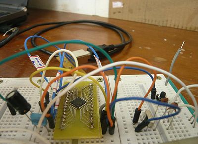
With the reset button on the right edge of the bread board. | |||
[[File:Yaac.jpg|400px]] | |||
== Schematic == | == Schematic == | ||
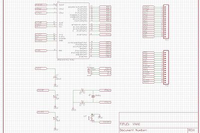
Basically, the AT90USB162, a couple of connectors, a 16MHz Oscillator, a few capacitors and a reset button. TODO upload the Eagle Cadsoft files to Github. | |||
[[File:Yacc_schematic.jpg|400px]] | |||
== PCB == | == PCB == | ||
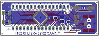
===Both layers=== | |||
[[File:Yacc_pcb.jpg|400px]] | |||
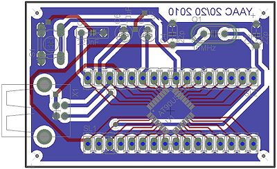
The YAAC, one USB Type B socket, one reset button, one crystal oscillator, five capacitors, one AT90USB162 and a couple of pin strips. | |||
===Bottom layer=== | |||
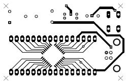
[[File:Yaacbottom.jpg]] | |||
===Top layer=== | |||
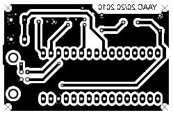
Mirrored to match bottom layer, when turned over face to face. | |||
[[File:Yaactop.jpg]] | |||
== PCB v2 == | |||
===Both layers=== | |||
[[File:Yaac2020.v4.jpg|400px]] | |||
The YAAC after a few more iterations. | |||
== BOM == | |||
Part Value Device Package Description | |||
C3 22p C-US050-024X044 C050-024X044 CAPACITOR, American symbol | |||
C4 22p C-US050-024X044 C050-024X044 CAPACITOR, American symbol | |||
C5 1uF CPOL-USE1.8-4 E1,8-4 POLARIZED CAPACITOR, American symbol | |||
C6 10uF CPOL-USE1.8-4 E1,8-4 POLARIZED CAPACITOR, American symbol | |||
C7 220nF C-US050-025X075 C050-025X075 CAPACITOR, American symbol | |||
Q1 16MHz CRYSTALHC49S HC49/S CRYSTAL | |||
S1 10-XX B3F-10XX OMRON SWITCH | |||
SL1 M16 16P AMP QUICK CONNECTOR | |||
SL2 M16 16P AMP QUICK CONNECTOR | |||
U1 AT90USB162-16AU AT90USB162-16AU VQFP32 | |||
X1 USB-B-H USB-B-H USB Connectors | |||
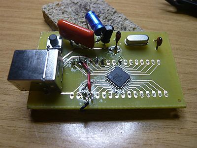
== First assembly == | |||
[[File:Yaac_assembled.jpg|400px]] | |||
The working YAAC, with a few design errors patched on-board. | |||
Lessons learnt: | |||
# Do not design in a hurry | |||
# Drill with 0.8mm drill bits only - the one I used (probably 1mm or thicker) lifted the copper. | |||
# Refer to BOM before laying out PCB. | |||
# Best printed straight from eagle to media, via pdf caused design to shrink, rendering pin strip pads unusable ("Samthetetchie" pointed out this could have been the pdf auto-adjusting to fit page width, or something in those lines, so jury still out on the pdf route). | |||
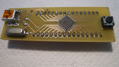
== Third assembly == | |||
[[File:Yaac2020.v4.assembled.jpg|400px]] | |||
Yet another (improved) version, the same breakout with more SMD components. | |||
General notes: | |||
# Vias drilled with 0.5mm drill bit, soldered to a twisted three-strand wire. | |||
# Pin strip holes drilled in two hits, first 0.7mm, second 0.9mm. This was to avoid copper being lifted by 0.9mm drill bit. | |||
# Used solder paste for the first time (67/33 tin/lead mix - no signs of lead poisoning yet, note to self, revisit this page in 2031 to update). Dispensing was disastrous but once hot air was blown everything fell into place - nice bonus. | |||
# Electrolytic capacitor positive end has a light brown stripe (they are on the board's underside and not visible on photo). | |||
# Apply air gently - one capacitor almost went airborne. | |||
# Ready state easily identifiable as solder paste colour changes from dark grey to silver. | |||
# Pins 31 (UVCC) and 32 (AVCC) need to be tied together. | |||
== Software required == | == Software required == | ||
* Arduino IDE - to compile sketches.<br> | * Arduino IDE - to compile sketches.<br> | ||
* Teensyduino Arduino IDE | * Teensyduino Arduino IDE addon - to list the Teensy on the Arduino IDE.<br> | ||
* Teensy loader - the Teensy GUI, this actually needs to be running otherwise the Arduino IDE will not compile sketches.<br> | * Teensy loader - the Teensy GUI, this actually needs to be running otherwise the Arduino IDE will not compile sketches.<br> | ||
* dfu programmer - to burn the actual code (hex file) onto the AT90USB162.<br> | * dfu programmer - to burn the actual code (hex file) onto the AT90USB162.<br> | ||
| Line 41: | Line 120: | ||
=== Installation === | === Installation === | ||
* Arduino | * Arduino (arduino-0018) | ||
$ sudo apt-get update | $ sudo apt-get update | ||
$ sudo apt-get install arduino | $ sudo apt-get install arduino | ||
* Teensyduino | * Teensyduino | ||
$ wget http://www.pjrc.com/teensy/teensyduino-0018 | |||
$ chmod +x teensyduino-0018 | |||
$ ./teensyduino-0018 | |||
Note: The teensyduino install will ask for the arduino-0018 installation folder. | |||
* Teensy loader | * Teensy loader | ||
$ wget http://www.pjrc.com/teensy/teensy.gz | $ wget http://www.pjrc.com/teensy/teensy.gz | ||
$ gunzip teensy.gz | |||
$ chmod +x teensy | |||
$ ./teensy | |||
* Arduino IDE | |||
$ cd | $ cd ~/arduino-0018 | ||
$ ./arduino | |||
$ ./ | |||
* dfu programmer | * dfu programmer | ||
$ sudo apt-get install dfu-programmer | $ sudo apt-get install dfu-programmer | ||
== Programming the YAAC == | == Programming the YAAC == | ||
| Line 85: | Line 165: | ||
(...)<br> | (...)<br> | ||
The YACC at this point should not be listed | The YACC at this point should not be listed because the device needs to be reset first.<br> | ||
Push the reset button | Push the reset button then run lsusb again.<br> | ||
$ lsusb | $ lsusb | ||
| Line 104: | Line 184: | ||
=== Running sketches and generating hex code === | === Running sketches and generating hex code === | ||
Sketches are run on the Arduino IDE, as per normal usage, piggybacking on the Teensy to make the Arduino IDE believe there is indeed a compatible device attached. This will generate a hex file in your /tmp directory. That is the code that needs to be burnt into the YAAC. | |||
The steps: | |||
# Start the teensy loader | |||
# Start the Arduino IDE | |||
# Select the Teensyduino device from menu Tools > Board > Teensy 1 (USB Serial) | |||
# Write code | |||
# Click verify | |||
All being well, the hex file is now in the /tmp directory. | |||
=== Burning hex code === | === Burning hex code === | ||
| Line 111: | Line 200: | ||
From the prompt run:<br> | From the prompt run:<br> | ||
$ sudo dfu-programmer at90usb162 erase | $ sudo dfu-programmer at90usb162 erase | ||
$ sudo dfu-programmer at90usb162 flash --debug 20 /tmp/build<...>.tmp/<filename>.cpp.hex | $ sudo dfu-programmer at90usb162 flash --debug 20 /tmp/build<...>.tmp/<filename>.cpp.hex | ||
$ sudo dfu-programmer at90usb162 start | $ sudo dfu-programmer at90usb162 start | ||
Note, the device must be reset before proceeding with the 3 steps above. Also, AFAIK, you must be root to access the USB device. If you forget sudo, strange things might happen e.g. code not burning, device not erasing and starting, etc, though no error message will be given - it will fail silently. | |||
Investigate adding UDEVs: http://www.pjrc.com/teensy/rawhid.html | |||
SUBSYSTEMS=="usb", ATTRS{idVendor}=="16c0", ATTRS{idProduct}=="0480", MODE:="0666" | |||
=== Serial communication over USB === | |||
Arduino Serial.begin() and Serial.print() statements are understood by the AT90USB162 libraries. Statements will be echoed to the Arduino's Serial Monitor, once the correct Serial Port - USB device mapping has been selected in the Arduino IDE: | |||
Tools > Serial Port > ''USB Device'' e.g. /dev/ttyUSB000 | |||
TODO: Look at generated .cpp files to see what functions Arduino Serial functions are mapping to. | |||
=== PWM === | |||
To get PWM to dim/brighten a LED, pick a PWM enabled pin and write analog values to it: | |||
<pre> | |||
// as per datasheet & Arduino IDE x AT90USB162 pin mapping | |||
byte PWM_pin = 15; | |||
// set to output | |||
pinMode(PWM_pin, OUTPUT); | |||
// write a varying value to the pin, in | |||
// this case I chose a compass angle. | |||
analogWrite(PWM_pin, angle); | |||
</pre> | |||
It so happens that angle varies between 0 and +180. The full PWM range, as per arduino.cc documentation, is between 0 and 255. | |||
== Potential improvements == | == Potential improvements == | ||
| Line 121: | Line 237: | ||
Lots of room for improvement: | Lots of room for improvement: | ||
* Getting Serial.print() to work | * <s>Getting Serial.print() to work</s> Thanks to Solexious. | ||
* Getting the actual YAAC listed on the Arduino IDE, instead of the Teensy. | * Getting the actual YAAC listed on the Arduino IDE, instead of the Teensy. | ||
* Burning code straight from the Arduino IDE onto the YAAC | * Burning code straight from the Arduino IDE onto the YAAC. | ||
* Use all SMD components, doubled sided board, shield compatible format. | * Use all SMD components, doubled sided board, shield compatible format. | ||
* Apply solder mask. | |||
* Produce a laser cut stencil for solder paste. | |||
* Add the silk screen layer. | |||
* Add real vias - through-hole platting would be ideal. | |||
* Use mini USB connector. | |||
[[Category:Projects]] | |||
Latest revision as of 01:07, 29 May 2013
Project maintained by Daniel Sikar ~/ dsikaratgmaildotcom.
| YAAC
| |
|---|---|
| QR code |
Project Brief
Summary
YAAC - Yet Another Arduino Clone. Based on Atmel's AT90USB162. Low part count. Cheap to build.
Overview
This is something I started developing above the 20/20 Archery Club, the previous London Hackspace address. It is based on three projects, the Benito 7, Nanduino and Teensy. You can run sketches on this device, though getting to burn actual code onto the YAAC is not as straightforward as with *real* Arduinos.
On the host side, for this specific project, I am running Ubuntu 10.04. It will probably run on other Debian based distributions without hickups. I don't know about Macs. I have burnt code on the YAAC running Windows Vista SP3 on the host, using the AVR toolchain - as per Benito 7 and Nanduino recipes. I don't know about running the Arduino IDE on Windows (TODO - find out).
Logo
Logo placeholder.
Motivation
1. Gaining experience with SMD components (AT90USB162).
2. Building a cheap device that can be programmed via USB.
3. Working with Atmel microcontrollers.
4. Being able to tap into the growing Wiring code examples.
Prototype
With the reset button on the right edge of the bread board.
Schematic
Basically, the AT90USB162, a couple of connectors, a 16MHz Oscillator, a few capacitors and a reset button. TODO upload the Eagle Cadsoft files to Github.
PCB
Both layers
The YAAC, one USB Type B socket, one reset button, one crystal oscillator, five capacitors, one AT90USB162 and a couple of pin strips.
Bottom layer
Top layer
Mirrored to match bottom layer, when turned over face to face.
PCB v2
Both layers
The YAAC after a few more iterations.
BOM
Part Value           Device          Package      Description
C3   22p             C-US050-024X044 C050-024X044 CAPACITOR, American symbol
C4   22p             C-US050-024X044 C050-024X044 CAPACITOR, American symbol
C5   1uF             CPOL-USE1.8-4   E1,8-4       POLARIZED CAPACITOR, American symbol
C6   10uF            CPOL-USE1.8-4   E1,8-4       POLARIZED CAPACITOR, American symbol
C7   220nF           C-US050-025X075 C050-025X075 CAPACITOR, American symbol
Q1   16MHz           CRYSTALHC49S    HC49/S       CRYSTAL
S1                   10-XX           B3F-10XX     OMRON SWITCH
SL1                  M16             16P          AMP QUICK CONNECTOR
SL2                  M16             16P          AMP QUICK CONNECTOR
U1   AT90USB162-16AU AT90USB162-16AU VQFP32
X1                   USB-B-H         USB-B-H      USB Connectors
First assembly
The working YAAC, with a few design errors patched on-board.
Lessons learnt:
- Do not design in a hurry
- Drill with 0.8mm drill bits only - the one I used (probably 1mm or thicker) lifted the copper.
- Refer to BOM before laying out PCB.
- Best printed straight from eagle to media, via pdf caused design to shrink, rendering pin strip pads unusable ("Samthetetchie" pointed out this could have been the pdf auto-adjusting to fit page width, or something in those lines, so jury still out on the pdf route).
Third assembly
Yet another (improved) version, the same breakout with more SMD components.
General notes:
- Vias drilled with 0.5mm drill bit, soldered to a twisted three-strand wire.
- Pin strip holes drilled in two hits, first 0.7mm, second 0.9mm. This was to avoid copper being lifted by 0.9mm drill bit.
- Used solder paste for the first time (67/33 tin/lead mix - no signs of lead poisoning yet, note to self, revisit this page in 2031 to update). Dispensing was disastrous but once hot air was blown everything fell into place - nice bonus.
- Electrolytic capacitor positive end has a light brown stripe (they are on the board's underside and not visible on photo).
- Apply air gently - one capacitor almost went airborne.
- Ready state easily identifiable as solder paste colour changes from dark grey to silver.
- Pins 31 (UVCC) and 32 (AVCC) need to be tied together.
Software required
- Arduino IDE - to compile sketches.
- Teensyduino Arduino IDE addon - to list the Teensy on the Arduino IDE.
- Teensy loader - the Teensy GUI, this actually needs to be running otherwise the Arduino IDE will not compile sketches.
- dfu programmer - to burn the actual code (hex file) onto the AT90USB162.
Installation
- Arduino (arduino-0018)
$ sudo apt-get update
$ sudo apt-get install arduino
- Teensyduino
$ wget http://www.pjrc.com/teensy/teensyduino-0018
$ chmod +x teensyduino-0018
$ ./teensyduino-0018
Note: The teensyduino install will ask for the arduino-0018 installation folder.
- Teensy loader
$ wget http://www.pjrc.com/teensy/teensy.gz
$ gunzip teensy.gz
$ chmod +x teensy
$ ./teensy
- Arduino IDE
$ cd ~/arduino-0018
$ ./arduino
- dfu programmer
$ sudo apt-get install dfu-programmer
Programming the YAAC
Enumerating
Once connected, from the prompt run lsusb (list USB devices):
$ lsusb
which should generate a list such as:
Bus 005 Device 002: ID 044e:300d Alps Electric Co., Ltd Bluetooth Controller (ALPS/UGPZ6)
Bus 005 Device 001: ID 1d6b:0001 Linux Foundation 1.1 root hub
Bus 004 Device 002: ID 0483:2016 SGS Thomson Microelectronics Fingerprint Reader
Bus 004 Device 001: ID 1d6b:0001 Linux Foundation 1.1 root hub
(...)
The YACC at this point should not be listed because the device needs to be reset first.
Push the reset button then run lsusb again.
$ lsusb
This time, all being well, an Atmel device should enumerate:
Bus 005 Device 002: ID 044e:300d Alps Electric Co., Ltd Bluetooth Controller (ALPS/UGPZ6)
Bus 005 Device 001: ID 1d6b:0001 Linux Foundation 1.1 root hub
Bus 004 Device 002: ID 0483:2016 SGS Thomson Microelectronics Fingerprint Reader
Bus 004 Device 001: ID 1d6b:0001 Linux Foundation 1.1 root hub
Bus 003 Device 001: ID 1d6b:0001 Linux Foundation 1.1 root hub
Bus 002 Device 003: ID 03eb:2ffa Atmel Corp.
(...)
That is the YAAC.
Running sketches and generating hex code
Sketches are run on the Arduino IDE, as per normal usage, piggybacking on the Teensy to make the Arduino IDE believe there is indeed a compatible device attached. This will generate a hex file in your /tmp directory. That is the code that needs to be burnt into the YAAC.
The steps:
- Start the teensy loader
- Start the Arduino IDE
- Select the Teensyduino device from menu Tools > Board > Teensy 1 (USB Serial)
- Write code
- Click verify
All being well, the hex file is now in the /tmp directory.
Burning hex code
From the prompt run:
$ sudo dfu-programmer at90usb162 erase
$ sudo dfu-programmer at90usb162 flash --debug 20 /tmp/build<...>.tmp/<filename>.cpp.hex
$ sudo dfu-programmer at90usb162 start
Note, the device must be reset before proceeding with the 3 steps above. Also, AFAIK, you must be root to access the USB device. If you forget sudo, strange things might happen e.g. code not burning, device not erasing and starting, etc, though no error message will be given - it will fail silently.
Investigate adding UDEVs: http://www.pjrc.com/teensy/rawhid.html
SUBSYSTEMS=="usb", ATTRS{idVendor}=="16c0", ATTRS{idProduct}=="0480", MODE:="0666"
Serial communication over USB
Arduino Serial.begin() and Serial.print() statements are understood by the AT90USB162 libraries. Statements will be echoed to the Arduino's Serial Monitor, once the correct Serial Port - USB device mapping has been selected in the Arduino IDE:
Tools > Serial Port > USB Device e.g. /dev/ttyUSB000
TODO: Look at generated .cpp files to see what functions Arduino Serial functions are mapping to.
PWM
To get PWM to dim/brighten a LED, pick a PWM enabled pin and write analog values to it:
// as per datasheet & Arduino IDE x AT90USB162 pin mapping
byte PWM_pin = 15;
// set to output
pinMode(PWM_pin, OUTPUT);
// write a varying value to the pin, in
// this case I chose a compass angle.
analogWrite(PWM_pin, angle);
It so happens that angle varies between 0 and +180. The full PWM range, as per arduino.cc documentation, is between 0 and 255.
Potential improvements
Lots of room for improvement:
Getting Serial.print() to workThanks to Solexious.- Getting the actual YAAC listed on the Arduino IDE, instead of the Teensy.
- Burning code straight from the Arduino IDE onto the YAAC.
- Use all SMD components, doubled sided board, shield compatible format.
- Apply solder mask.
- Produce a laser cut stencil for solder paste.
- Add the silk screen layer.
- Add real vias - through-hole platting would be ideal.
- Use mini USB connector.

