LED tiles V2: Difference between revisions
(adding from mailing list thread to date) |
m (Add link to Limehouse Labs site) |
||
| (22 intermediate revisions by 3 users not shown) | |||
| Line 1: | Line 1: | ||
[[File:LED tile v2 hackspace logo.jpg|300px|thumb|right|Four LED tiles displaying the hackspace logo.]] | |||
LED screen tiles donated by Tom (Mistamudd) | LED screen tiles donated by Tom (Mistamudd) | ||
[https://groups.google.com/forum/#!topic/london-hack-space/RZeO143uh7A See mailing list thread here.] | [https://groups.google.com/forum/#!topic/london-hack-space/RZeO143uh7A See mailing list thread here.] | ||
[[File:LED Tile V2.jpg| | |||
The majority of these tiles were re-distributed around the UK by Limehouse Labs in 2023. [https://led.limehouselabs.org/docs/tiles/led-tiles-v2/ More info on the Limehouse Labs site]. | |||
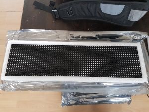
[[File:LED Tile V2.jpg|300px|thumb|right|LED tile in its packaging.]] | |||
== Specs == | == Specs == | ||
| Line 7: | Line 12: | ||
Each tile is 500mm wide x 125mm high with LED pixels every 7mm pitch. | Each tile is 500mm wide x 125mm high with LED pixels every 7mm pitch. | ||
There are 48 x MBI5034 LED controller chips on the PCB, which are 16 bit shift register constant current sinks. Datasheet : [[File:MBI5034 Datasheet VA.00-EN.pdf]] | There are 48 x MBI5034 LED controller chips on the PCB, which are 16 bit shift register constant current sinks. Datasheet : [[File:MBI5034 Datasheet VA.00-EN.pdf]] | ||
| Line 20: | Line 23: | ||
There are also 8 dual FET chips, which seem to control the 4 banks. | There are also 8 dual FET chips, which seem to control the 4 banks. | ||
=== Panel connectors === | |||
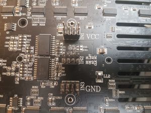
[[File:LED Tile Pinout.jpg|thumb|right|300px|Pinouts]] | |||
The bottom | The top connector is all Vcc (5v). Half the pins power the top half of the panel. The other half power the bottom half of the panel. To light the whole panel, you need to power all 8 Vcc pins. | ||
The middle connector has : | The middle connector has : | ||
{|class="wikitable" | |||
|- | |||
|D1||LAT (Latch)||A1||NC | |||
|- | |||
|D2||OE||A0||CLK (Clock) | |||
|} | |||
The bottom is all ground. | |||
== Mechanical Drawings == | |||
== | [[File:LED Panel - QCAD with guidelines - FINAL.png|600px]] | ||
The DXF file of the mechanical drawing, created in QCAD, with guidelines - [[File:LED Panel - QCAD with guideliness - FINAL.dxf]] | |||
The DXF file of a four panel mounting bracket, for 4x1 panels (500mm x 500mm / 64x64 pixels in total) created in QCAD, ready for laser cutting - [[File:LED Panel x4 - QCAD for laser cutter.dxf]] | |||
== Arduino == | |||
Can be driven with an Arduino or Teensy. The data pins can be driven directly with 3.3V and the panel fully on pulls about 7 amps @ 5v. | Can be driven with an Arduino or Teensy. The data pins can be driven directly with 3.3V and the panel fully on pulls about 7 amps @ 5v. | ||
== | === Coding === | ||
The serial data sent to D1 & D2 needs to be sent in 3 x 16 bit B,G,R frames, 64 times per row (i.e. one row is 384 bits) then this is latched, and then the output is enabled. | The serial data sent to D1 & D2 needs to be sent in 3 x 16 bit B,G,R frames, 64 times per row (i.e. one row is 384 bits) then this is latched, and then the output is enabled. | ||
| Line 57: | Line 73: | ||
[[File:LED Panel Bit Stream.png]] | [[File:LED Panel Bit Stream.png]] | ||
=== Driving four panels === | |||
Make sure you have 8+ Amps @ 5v per Panel. Minimum 32 Amps for 4 panels. | |||
The wiring for the middle connectors is: | |||
{|class="wikitable" | |||
!Arduino pins!!Panel pins | |||
|- | |||
|Digital 3||D1 on panel 1 | |||
|- | |||
|Digital 2||D2 on panel 1 | |||
|- | |||
|Digital 0||D1 on panel 2 | |||
|- | |||
|Digital 1||D2 on panel 2 | |||
|- | |||
|Digital 8||D1 on panel 3 | |||
|- | |||
|Digital 9||D2 on panel 3 | |||
|- | |||
|Digital 10||D1 on panel 4 | |||
|- | |||
|Digital 11||D2 on panel 4 | |||
|- | |||
|Analogue 4||A0 on all panels | |||
|- | |||
|Analogue 1||A1 on all panels | |||
|- | |||
|Analogue 3||CLK on all panels | |||
|- | |||
|Analogue 2||LAT on all panels | |||
|- | |||
|Analogue 5||OE on all panels | |||
|- | |||
|} | |||
== Ready made LED Scancards == | |||
LED Scancards (receiving cards) are available from [http://www.led-card.com/ LED-CARD Store]. Tom recommends those from Novastar although others, e.g. Linsn, DBStar, etc. should still work. | |||
The control software from Novastar (Nova Mars) is by far the most friendly and widely used LED panel control software, [https://www.dropbox.com/s/17r9j3b2ycbif82/NovaLCT-Mars%20V4.4.1%20Setup.exe?dl=0 NovaLCT-Mars V4.4.1 Setup.exe] and [https://www.dropbox.com/s/xutbswt1c742isb/Nova%20Mars%20-%20LED%20Control%20Software%20User%20Manual%20v1.6.pdf?dl=0 User manual]. | |||
If you buy a LED screen from DigiLED they will give you a pre-made config file called an rcfg file. This is the file that configures the Scancard to work with a given design of LED tile. However because this isn't a standard digiLED product Tom cant share a ready made file with you. Instead, you need to create the file yourself. | |||
This is done from the Receiving Card Tab of the Screen Configuration menu. Look for a menu called "Smart Settings". | |||
Smart settings will walk you through a wizard where you click-in the multiplex/scan info, the RGB order info and the pixel map info of the LED tile, all guided by lit up sections of the LED tile and click responses in Mars. The end result of this process is a newly created rcfg file that will configure your Scancard of choice to you LED tile of choice. | |||
=== Which card? === | |||
Tom recommends you start with the [http://www.led-card.com/novastar-mrv336-led-display-receptor.html Novastar MRV336 LED Display receptor] because it's cheap and can do lots and lots of LED tiles on one card. | |||
You are also going to need a [http://www.led-card.com/novastar-msd300-led-display-decoder.html Novastar MSD300 LED display decoder] or [http://www.led-card.com/novastar-mctrl300-led-real-time-sending-box.html Novastar MCTRL300 LED real time sending box] to act as your DVI to LED panel converter. | |||
With this little bundle of kit you literally have enough to map a 64x16 pixel slice of your computer desktop straight onto the LED tiles at full video quality and frame-rate. Add more LED tiles for bigger pixel space. Copy Paste Repeat and you could take this all the way to 4k width or height although a screen with these pixels at 4k size would be mahussive!!! | |||
== External links == | == External links == | ||
* Google Groups thread ''[https://groups.google.com/d/topic/london-hack-space/RZeO143uh7A/discussion Donation (if wanted) - LED Screen Tiles]'' | |||
* [https://github.com/JonRussell00/LEDpanels Arduino code for driving 4 panels] - uses AdaFruit GFX library by Oliver Dewdney and Jon Russell | |||
* [https://www.arduino.cc/en/Main/ArduinoBoardMicro?setlang=en Arduino Micro] | |||
* Las Vegas Hackspace (Synshop) [https://github.com/krux702/led_panel_wall LED panel wall] project on GitHub, (includes a high res image of the PCB). | * Las Vegas Hackspace (Synshop) [https://github.com/krux702/led_panel_wall LED panel wall] project on GitHub, (includes a high res image of the PCB). | ||
[[Category:LED tiles]] | [[Category:LED tiles]] | ||
Latest revision as of 21:39, 26 September 2023
LED screen tiles donated by Tom (Mistamudd) See mailing list thread here.
The majority of these tiles were re-distributed around the UK by Limehouse Labs in 2023. More info on the Limehouse Labs site.
Specs
The tile contains the matrix of 64 x 16 (1024) RGB LEDs and the driver ICs. Data is sent serially to the LEDs, configured in 'banks' and 'rows'.
Each tile is 500mm wide x 125mm high with LED pixels every 7mm pitch.
There are 48 x MBI5034 LED controller chips on the PCB, which are 16 bit shift register constant current sinks. Datasheet : File:MBI5034 Datasheet VA.00-EN.pdf
The controller chips are labelled R,G & B 1-16. So each chip does 16 LEDs of the same colour. They each have a current set resistor. You can also set the current gain in software from 12.5% to 200% but this set the gain for all LEDs attached to that chip, not individual LEDs. The default power gain is 100%.
There are two address line inputs and the LED chips seem to be soldered in to banks of 4. Which makes sense.
There is an HC138 decoder on the address lines, and only the first four outputs seem to be wired. Again, matches the above.
There are also 8 dual FET chips, which seem to control the 4 banks.
Panel connectors
The top connector is all Vcc (5v). Half the pins power the top half of the panel. The other half power the bottom half of the panel. To light the whole panel, you need to power all 8 Vcc pins.
The middle connector has :
| D1 | LAT (Latch) | A1 | NC |
| D2 | OE | A0 | CLK (Clock) |
The bottom is all ground.
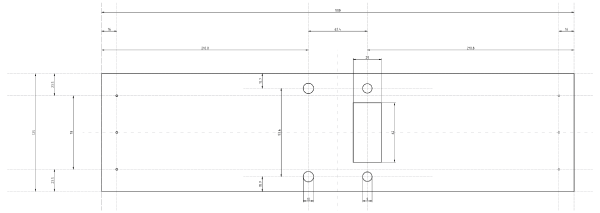
Mechanical Drawings
The DXF file of the mechanical drawing, created in QCAD, with guidelines - File:LED Panel - QCAD with guideliness - FINAL.dxf
The DXF file of a four panel mounting bracket, for 4x1 panels (500mm x 500mm / 64x64 pixels in total) created in QCAD, ready for laser cutting - File:LED Panel x4 - QCAD for laser cutter.dxf
Arduino
Can be driven with an Arduino or Teensy. The data pins can be driven directly with 3.3V and the panel fully on pulls about 7 amps @ 5v.
Coding
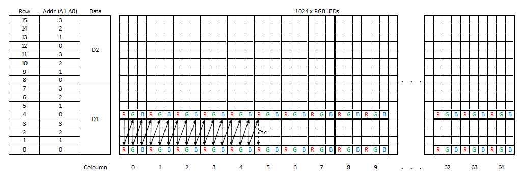
The serial data sent to D1 & D2 needs to be sent in 3 x 16 bit B,G,R frames, 64 times per row (i.e. one row is 384 bits) then this is latched, and then the output is enabled.
BBBBBBBB BBBBBBBB GGGGGGGG GGGGGGGG RRRRRRRR RRRRRRR | BBBBBBBB BBBBBBBB GGGGGGGG GGGGGGGG RRRRRRRR RRRRRRR | BBBBBBBB BBBBBBBB GGGGGGGG GGGGGGGG RRRRRRRR RRRRRRR ... etc .. x 384 bits
There are two 'banks'; the top 8 rows and bottom 8 rows. There are loaded with data using two different data in lines, D1 & D2. The data lines are clocked and latched with the same shared clock and latch signals.
In each bank, there are 8 rows. A single stream of 384 bits loads two rows of 2 x 64 LEDs. The address lines A0 & A1 select which row is being loaded from the serial data.
To display a full tile, of all 1024 RGB LEDs, you need to :
- Set OE=HIGH & LAT=LOW
- For each address A0 & A1 = 0x00. 0x01. 0x10. 0x1 :
- Clock 384 bits of data on to D1 & D2, by toggling the CLK pin from LOW to HIGH
- Toggling LAT pin from HIGH to LOW to latch the 384 bits in to the driver chips.
- Toggle the OE pin LOW to turn the LEDs on for that row.
- Clock 4 x 384 bits of data to light every row of LEDs in sequence.
Repeat this very quickly as fast as you can ! :-)
The LEDs are either on or off, there is no brightness control of individual LEDs possible. To mix colours, you need to implement a PWM or BCM waveform with each refresh cycle of the panel.
Driving four panels
Make sure you have 8+ Amps @ 5v per Panel. Minimum 32 Amps for 4 panels.
The wiring for the middle connectors is:
| Arduino pins | Panel pins |
|---|---|
| Digital 3 | D1 on panel 1 |
| Digital 2 | D2 on panel 1 |
| Digital 0 | D1 on panel 2 |
| Digital 1 | D2 on panel 2 |
| Digital 8 | D1 on panel 3 |
| Digital 9 | D2 on panel 3 |
| Digital 10 | D1 on panel 4 |
| Digital 11 | D2 on panel 4 |
| Analogue 4 | A0 on all panels |
| Analogue 1 | A1 on all panels |
| Analogue 3 | CLK on all panels |
| Analogue 2 | LAT on all panels |
| Analogue 5 | OE on all panels |
Ready made LED Scancards
LED Scancards (receiving cards) are available from LED-CARD Store. Tom recommends those from Novastar although others, e.g. Linsn, DBStar, etc. should still work.
The control software from Novastar (Nova Mars) is by far the most friendly and widely used LED panel control software, NovaLCT-Mars V4.4.1 Setup.exe and User manual.
If you buy a LED screen from DigiLED they will give you a pre-made config file called an rcfg file. This is the file that configures the Scancard to work with a given design of LED tile. However because this isn't a standard digiLED product Tom cant share a ready made file with you. Instead, you need to create the file yourself.
This is done from the Receiving Card Tab of the Screen Configuration menu. Look for a menu called "Smart Settings".
Smart settings will walk you through a wizard where you click-in the multiplex/scan info, the RGB order info and the pixel map info of the LED tile, all guided by lit up sections of the LED tile and click responses in Mars. The end result of this process is a newly created rcfg file that will configure your Scancard of choice to you LED tile of choice.
Which card?
Tom recommends you start with the Novastar MRV336 LED Display receptor because it's cheap and can do lots and lots of LED tiles on one card.
You are also going to need a Novastar MSD300 LED display decoder or Novastar MCTRL300 LED real time sending box to act as your DVI to LED panel converter.
With this little bundle of kit you literally have enough to map a 64x16 pixel slice of your computer desktop straight onto the LED tiles at full video quality and frame-rate. Add more LED tiles for bigger pixel space. Copy Paste Repeat and you could take this all the way to 4k width or height although a screen with these pixels at 4k size would be mahussive!!!
External links
- Google Groups thread Donation (if wanted) - LED Screen Tiles
- Arduino code for driving 4 panels - uses AdaFruit GFX library by Oliver Dewdney and Jon Russell
- Arduino Micro
- Las Vegas Hackspace (Synshop) LED panel wall project on GitHub, (includes a high res image of the PCB).
