Project:Traffic Lights: Difference between revisions
m (Marrold moved page Project:TrafficLights to Project:Traffic Lights) |
No edit summary |
||
| Line 1: | Line 1: | ||
'''Warning: You should read and understand this document ''in full'' before opening or hacking on the traffic light''' | |||
'''Please speak with [[User:marrold|marrold]] prior to hacking to find out the current status of the Project.''' | |||
[[File:TrafficLightOutside.JPG|250px|thumb|right|Traffic Light]] | |||
=== Safety === | |||
* '''Mains voltage''' is present in the traffic light. | |||
* '''Always''' isolate the power before opening up any of the sections. | |||
* '''Always''' isolate the power before programming the ESP8285 - otherwise your risk damaging your computer or yourself. | |||
=== Hardware === | |||
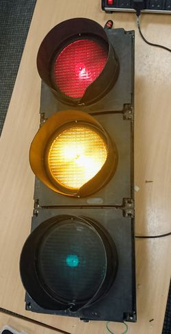
The traffic light is a PEEK Elite Traffic Light in a RAG (Red - Amber - Green) configuration, manufactured around 2001. It's currently fitted with Pedestrian hoods as these are more compact than the Primary or Secondary hoods. | |||
=== Controller === | |||
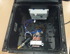
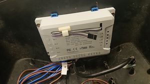
The traffic light is controlled by a [https://www.itead.cc/wiki/Sonoff_4CH "Sonoff 4CH"] 4 channel relay board, a commercially available device that costs around £15-25. The relay board itself is controlled by an Espressif ESP8285 System on Chip (SoC), which is almost identical to the popular ESP8266, but contains additional memory. The ESP8285 has onboard WiFi and supports the Arduino platform and libraries, making it ideal for an "IoT" device. | |||
=== Wiring === | |||
The traffic light is powered from 90-250v AC (50/60Hz). The controller contains an AC-DC convertor to bring it down to the 3.3V required by the ESP8285. The 4 relays output mains voltage, which is then dropped down to ~12v AC by an individual transformer ''per bulb''. | |||
=== Bulbs === | |||
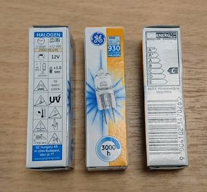
The "real" bulbs for these traffic lights are 12V, 50W Halogen Bulbs with a GY6.35 base from General Electric, however they have been replaced with generic 4W LED bulbs to reduce the brightness and power consumption. | |||
The | === Programming === | ||
The Sonoff 4CH can be programmed via serial using the Arduino IDE, Platformio, or any other software capable of programming an ESP8285. | |||
To get into flashing mode, you must press and hold the L1 button down as you power up the board. | |||
Some USB to Serial adapters are unable to supply the required current to the Sonoff. If you see weird behaviour like the board restarting, you may need to power it externally with 3.3V (NOT MAINS!). | |||
{| class="wikitable" | |||
! style="font-weight:bold;" | Colour | |||
! style="font-weight:bold;" | Use | |||
|- | |||
| style="background-color:#cbcefb;" | Violet | |||
| style="background-color:#cbcefb;" | VCC (3.3V) | |||
|- | |||
| White | |||
| Tx | |||
|- | |||
| style="background-color:#c0c0c0;" | Grey | |||
| style="background-color:#c0c0c0;" | Rx | |||
|- | |||
| style="background-color:#000000; color:#ffffff;" | Black | |||
| style="background-color:#000000; color:#ffffff;" | Ground | |||
|} | |||
'''N.B: Remember to "invert" the UART connections''' | |||
=== Current Use === | |||
The traffic light currently cycles through the light cycle displayed at road junctions. | |||
== Pictures == | |||
{| | |||
| [[File:TrafficLightInside.JPG|thumb|Inside, showing the controller. ]] | |||
| [[File:TrafficLightController.JPG|thumb|A close up of the controller, showing the programming lead. ]] | |||
| [[File: TrafficLightBulbs.JPG|thumb|The "real" 50W GY6.35 bulbs.]] | |||
|} | |||
[[Category:Projects]] | [[Category:Projects]] | ||
[[Category:Space_Infrastructure_Projects]] | [[Category:Space_Infrastructure_Projects]] | ||
Revision as of 22:25, 8 February 2019
Warning: You should read and understand this document in full before opening or hacking on the traffic light
Please speak with marrold prior to hacking to find out the current status of the Project.
Safety
- Mains voltage is present in the traffic light.
- Always isolate the power before opening up any of the sections.
- Always isolate the power before programming the ESP8285 - otherwise your risk damaging your computer or yourself.
Hardware
The traffic light is a PEEK Elite Traffic Light in a RAG (Red - Amber - Green) configuration, manufactured around 2001. It's currently fitted with Pedestrian hoods as these are more compact than the Primary or Secondary hoods.
Controller
The traffic light is controlled by a "Sonoff 4CH" 4 channel relay board, a commercially available device that costs around £15-25. The relay board itself is controlled by an Espressif ESP8285 System on Chip (SoC), which is almost identical to the popular ESP8266, but contains additional memory. The ESP8285 has onboard WiFi and supports the Arduino platform and libraries, making it ideal for an "IoT" device.
Wiring
The traffic light is powered from 90-250v AC (50/60Hz). The controller contains an AC-DC convertor to bring it down to the 3.3V required by the ESP8285. The 4 relays output mains voltage, which is then dropped down to ~12v AC by an individual transformer per bulb.
Bulbs
The "real" bulbs for these traffic lights are 12V, 50W Halogen Bulbs with a GY6.35 base from General Electric, however they have been replaced with generic 4W LED bulbs to reduce the brightness and power consumption.
Programming
The Sonoff 4CH can be programmed via serial using the Arduino IDE, Platformio, or any other software capable of programming an ESP8285.
To get into flashing mode, you must press and hold the L1 button down as you power up the board.
Some USB to Serial adapters are unable to supply the required current to the Sonoff. If you see weird behaviour like the board restarting, you may need to power it externally with 3.3V (NOT MAINS!).
| Colour | Use |
|---|---|
| Violet | VCC (3.3V) |
| White | Tx |
| Grey | Rx |
| Black | Ground |
N.B: Remember to "invert" the UART connections
Current Use
The traffic light currently cycles through the light cycle displayed at road junctions.


