Project:Nanode/PoorMansCable2
Poor mans Arduino/ftdi cable
Requirements
1) Random no-name USB to Serial cable. In our case a Sitecom CN (http://www.sitecom.com/usb-to-serial-cable/p/31). Ideailly PL2303-XXX based. 2) Small plastic enclosure (http://www.maplin.co.uk/miniature-general-purpose-abs-box-1551-series-43710) 3) A 5 pin IDC which fits on the nanode its FTDI cable. I recycled one from a floppy disk which happened to fit.
Introduction
Virtually all low cost PL2303 USB/Serial connectors seem to be based on the reference design of Prolific:
http://www.prolific.com.tw/eng/downloads.asp?ID=58
And this means one of the PL2303 connected to the USB on the one side and providing a 5v serial TTL on the other; and then some RS-232 tranceiver (SP213EH) to lift TTL to RS232 voltages.
We're basically going to cut of the latter conversion - and directly use the 5v TTL from the PL2303.
Building
http://www.maplin.co.uk/miniature-general-purpose-abs-box-1551-series-43710
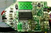
First use a sharp knife to cut the gummy off the DB95 end of the connector. Once cut open you'll find a small circuit board encased in hotglue Warm it a litte and gently pull it off. You are left with a clean circuit board.
On the board are two chips; one is the main USB chip and one is some MAX233/SP231 or similar variant which brings the 5v of the USB logic to the required RS232 voltages. We're now after the 5 FTDI wires:
|| serial || FTDI colour || DB9 pin || | RTS | green | DB9 - 7 | | RxD | yellow | DB9 - 2 | | TxD | orange | DB9 - 3 | | VCC | red | n/a | | CTS | brown | DB9 - 8 | | GND | black | DB9 - 5 |
(http://www.sparkfun.com/datasheets/DevTools/FTDI%203.3V%20IO%205V%20Vcc%20Cable.pdf)
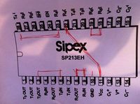
Use a multimeter to find the pin on the SP213EH to which the corresponding DB9 pin is wired. Note this on the diagram of the SP231EH chip:
http://www.datasheetcatalog.org/datasheet/sipex/SP213EHEA.pdf
On that same diagram - identify the corresponding 5 volt pin. E.g. if your RxD went to R2IN (pin 32) then the 5volt pin will be the R2OUT (pin 22).
For the +5v (VCC) we do a bit of a cheat - we wire it to one of the 'free' pins on the DB9 - so we can more easily solder a wire to it.
Now desolder the SP231 or MAX Rrs232 tranceiver chip. And then bridge the various IN and OUTs corresponding to your schematic.
Then remove the DB9 and wire up your FTDI connector. And put it all in a small box.
That is it really.

