Project:1-web-interfaces-for-rc-vehicles
| 1-web-interfaces-for-rc-vehicles
| |
|---|---|
| QR code |
Aim
Drive a r/c car in as near realtime as possible via a webinterface with a driver's POV wireless video feed.
Current Implementation Status / Operator's Log
19/11/10
- The car is working via IRC. Use ?board car1 or ?board car2 or ?board car3 etc
- Numbers 1 to 8 represent the different control characters available (see below for a breakdown of the 'sauce code').
- The battery is quite old and could do with replacing.
Who?
Special thanks to Chris Brooking.
What?
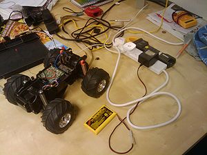
Some really old photos: https://picasaweb.google.com/110896145612785649027/1WebInterfaceForRemoteControlledVehicles r/c car + arduino + IRC + Python + webcams everywhere = awesome internet happy fun time.
1. Next time you are bored and in IRC have a look at the main webcam [1]
2. Ask someone currently in the space very nicely if they wouldn't mind plugging in the battery and turning on the r/c car and placing it in view of the webcam.
3. Then have a chat with robonaut with /msg robonaut ?board car5. If everything went to plan the car should have just gone forwards a bit.
4. For the current full set of commands please refer to the table below:
Commands
| Command | Result |
|---|---|
| ?board car1 | Drive forward and turn left. |
| ?board car2 | Drive forward and turn right. |
| ?board car3 | Drive backward and turn left. |
| ?board car4 | Drive backward and turn right. |
| ?board car5 | Drive forward. |
| ?board car6 | Drive backward. |
| ?board car7 | Turn wheels left (not latching, implemented only for testing). |
| ?board car8 | Turn wheels right (not latching, implemented only for testing). |
Calibration
- Movement Timing Calibration Values
#define FWD_TURN_TIME 1000
#define BACK_TURN_TIME 1000
#define DRIVE_TIME 1000
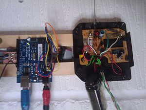
Arduino Shield Pinout
- Arduino Digital I/O pins
#define CAR_FWD 9       //White Cable
#define CAR_BACK 11     //Black Cable
#define CAR_LEFT 8      //Brown Cable
#define CAR_RIGHT 10    //Blue  Cable
There is also a digital ground pin (it is a black cable and it is on its own) attached to a chocolate block in order to allow sharing of the digital ground with other circuits on that arduino.
Sauce Code
The source is currently in an IF loop in the Solexious' NotifyBoard arduino sketch. Note: request upstream pull to github from local git repo on babbage or lovelace.
   if (strstr(inString,"car")) {
     if (strlen(inString) > 3) {
       char car_cmd = inString[3];
         switch (car_cmd){
         case '1':
           digitalWrite(CAR_LEFT, HIGH);
           digitalWrite(CAR_FWD, HIGH);
           delay(FWD_TURN_TIME);
           digitalWrite(CAR_LEFT, LOW);
           digitalWrite(CAR_FWD, LOW);
           break;
         case '2':
           digitalWrite(CAR_RIGHT, HIGH);
           digitalWrite(CAR_FWD, HIGH);
           delay(FWD_TURN_TIME);
           digitalWrite(CAR_RIGHT, LOW);
           digitalWrite(CAR_FWD, LOW);
           break;
         case '3':
           digitalWrite(CAR_LEFT, HIGH);
           digitalWrite(CAR_BACK, HIGH);
           delay(BACK_TURN_TIME);
           digitalWrite(CAR_LEFT, LOW);
           digitalWrite(CAR_BACK, LOW);
           break;
         case '4':
           digitalWrite(CAR_RIGHT, HIGH);
           digitalWrite(CAR_BACK, HIGH);
           delay(BACK_TURN_TIME);
           digitalWrite(CAR_RIGHT, LOW);
           digitalWrite(CAR_BACK, LOW);
           break;
         case '5':
           digitalWrite(CAR_FWD, HIGH);
           delay(DRIVE_TIME);
           digitalWrite(CAR_FWD, LOW);
           break;
         case '6':
           digitalWrite(CAR_BACK, HIGH);
           delay(DRIVE_TIME);
           digitalWrite(CAR_BACK, LOW);
           break;
         case '7':
           digitalWrite(CAR_LEFT, HIGH);
           delay(DRIVE_TIME);
           digitalWrite(CAR_LEFT, LOW);
           break;
         case '8':
           digitalWrite(CAR_RIGHT, HIGH);
           delay(DRIVE_TIME);
           digitalWrite(CAR_RIGHT, LOW);
           break;
       }
     }
   }
Where?
London Hackspace Lab 24: http://london.hackspace.org.uk/
Why?
Driving a car remotely over the internet is fun. This is not however funny in the case of a real car...
How?
Four digital I/Os from the arduino (11,10,9,8), each of which are connected to the gate of an NPN transistor to handle about 30mA switching current, simulate the pressing of the four push-to-make contact switches on a simple r/c car remote control. digitalWrite(pinX, HIGH); results in a pressed state and digitalWrite(pinX, LOW); results in an unpressed state. This effectively gives a digitally-controlled forward, backward, left and right switch for the remote control car. This concept can be applied to any cheap remote-controlled toy.
Development Milestones
1. Working via IRC using ?board car<command number> in 'less than realtime'. DONE
2. Working via a webpage babbage:80XX or /var/www/rcv or something like that in 'near realtime'.
3. Low quality but high refresh rate on-board wireless camera to suit real-time control interface.

