Difference between revisions of "Project:Cholten99/TimeTravel"
Jump to navigation
Jump to search
| Line 42: | Line 42: | ||
## Meter activated | ## Meter activated | ||
## Motor activated, forward | ## Motor activated, forward | ||
| + | ## Blue flashing light started | ||
# Top microswitch activated | # Top microswitch activated | ||
## Sound effect 1 stopped | ## Sound effect 1 stopped | ||
| Line 47: | Line 48: | ||
## Meter deactivated | ## Meter deactivated | ||
## Motor stopped | ## Motor stopped | ||
| + | ## Blue flashing light stopped | ||
## Light changed from green to red | ## Light changed from green to red | ||
# Switch moved from position 2 to position 1 | # Switch moved from position 2 to position 1 | ||
| Line 52: | Line 54: | ||
## Meter activated | ## Meter activated | ||
## Motor activated, backwards | ## Motor activated, backwards | ||
| + | ## Blue flashing light started | ||
# Bottom microswitch activated | # Bottom microswitch activated | ||
## Sound effect 1 stopped | ## Sound effect 1 stopped | ||
| Line 57: | Line 60: | ||
## Meter deactivated | ## Meter deactivated | ||
## Motor stopped | ## Motor stopped | ||
| + | ## Blue flashing light stopped | ||
## Light changed from red to green | ## Light changed from red to green | ||
| + | |||
| + | ===== Components ===== | ||
| + | |||
| + | # Switch (got!) | ||
| + | # Meter (got!) | ||
| + | # Red / green LED (and housing) | ||
| + | # Blue LED (and housing) | ||
| + | # Blue LED flashing circuit components (556 timer) | ||
| + | # Motor | ||
| + | # 9v battery (and holder) | ||
| + | # 2 microswitches | ||
| + | # NM52 chipcorder (for sounds) | ||
| + | # 16ohm speaker (for sounds) | ||
==== Motor / Gear System ==== | ==== Motor / Gear System ==== | ||
Revision as of 16:52, 25 March 2011
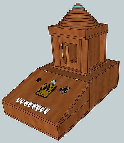
Time Travel Project
Potential Sketch
Major Stages
- Case
- Preliminary sketch created (DONE!)
- Design finalised
- Case materials purchased
- Case built
- Case 'polished'
- Dials
- Design finalised
- Components purchased
- Dials built
- Dials fixed into case
- Electronics
- Design complete
- Components purchased
- Circuit built
- Working in case
- Motor / gear system
- Design finished
- Components purchased
- System built into case
- Testing complete
- Sound effects
- Sound effects created (DONE!)
- Sound(s) recorded into chip
Case
Electronics
Sequence
- Switch moved from position 1 to position 2
- Sound effect 1 starts on loop
- Meter activated
- Motor activated, forward
- Blue flashing light started
- Top microswitch activated
- Sound effect 1 stopped
- Sound effect 2 played once
- Meter deactivated
- Motor stopped
- Blue flashing light stopped
- Light changed from green to red
- Switch moved from position 2 to position 1
- Sound effect 1 starts on loop
- Meter activated
- Motor activated, backwards
- Blue flashing light started
- Bottom microswitch activated
- Sound effect 1 stopped
- Sound effect 2 played once
- Meter deactivated
- Motor stopped
- Blue flashing light stopped
- Light changed from red to green
Components
- Switch (got!)
- Meter (got!)
- Red / green LED (and housing)
- Blue LED (and housing)
- Blue LED flashing circuit components (556 timer)
- Motor
- 9v battery (and holder)
- 2 microswitches
- NM52 chipcorder (for sounds)
- 16ohm speaker (for sounds)
Motor / Gear System
Sound Effects
Sound(s) found!
