Difference between revisions of "Project:HM55B"
(→Reset) |
|||
| Line 68: | Line 68: | ||
There should now be +5v measured between HM55B pins 3 and 6. | There should now be +5v measured between HM55B pins 3 and 6. | ||
| + | |||
| + | === Abridged command set == | ||
| + | |||
| + | To cover this use case: | ||
| + | |||
| + | <pre> | ||
| + | ? help | ||
| + | /\ Clock H/L ~ CLK pin | ||
| + | -/_ Data H/L ~ MOSI pin | ||
| + | ! Read bit ~ MISO pin | ||
| + | [] CS L/H ~ CS pin | ||
| + | & 1uS delay | ||
| + | : Repeat | ||
| + | </pre> | ||
=== Reset=== | === Reset=== | ||
| − | |||
| − | + | Reading in plain english, "Set clock pin to low, set CS pin to low, shift out b0000 on the rising edge of the clock, delay 1uS, repeat delay 10 times then set CS pin to high". | |
| + | |||
| + | Noting that CS maps to active low /EN pin. | ||
| + | |||
| + | \[/_\/_\/_\/_\] | ||
=== Take sample === | === Take sample === | ||
Revision as of 23:25, 11 December 2010
About the module
$20-25 compass module for embedded systems, this comes in a convenient DIL package.
The SMD will probably be cheaper, though I have not managed to source one yet.
Bus Pirate pinout
From http://dangerousprototypes.com/docs/Bus_Pirate_101_tutorial
Pin name Description (Bus Pirate is the master)
MOSI 	Master data out, slave in (SPI, JTAG), Serial data (1-Wire, I2C, KB), TX* (UART)
CLK 	Clock signal (I2C, SPI, JTAG, KB)
MISO 	Master data in, slave out (SPI, JTAG) RX (UART)
CS* 	Chip select (SPI), TMS (JTAG)
AUX 	Auxiliary IO, frequency probe, pulse-width modulator
ADC 	Voltage measurement probe (max 6volts)
Vpu 	Voltage input for on-board pull-up resistors (0-5volts).
+3.3v 	+3.3volt switchable power supply
+5.0v 	+5volt switchable power supply
GND 	Ground, connect to ground of test circuit
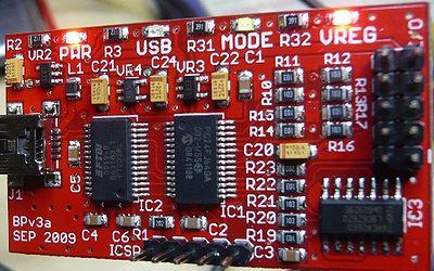
In the photo the pins on right connector, from top left:
GND  +3.3V
+5V  ADC
Vpu  AUX
CLK  MOSI
CS   MISO
Connecting
Wiring
HM55B   Bus Pirate

Din(1)  MOSI
Dout(2) MISO
VSS(3)  GND
CLK(4)  CLK
/EN(5)  CS
Vdd(6)  +5V
Starting a terminal session
Plug in the bus pirate then (assuming it's the only USB device plugged in a debian based os):
$ screen /dev/ttyUSB0 115200
Testing with the BusPirate
Once in the terminal session, apply these settings:
- M (mode)
- 8 (3-wire raw)
- 4 (400KHz)
- 2 (3.3V high)
- W (turn on 5V output)
Checkpoint
There should now be +5v measured between HM55B pins 3 and 6.
= Abridged command set
To cover this use case:
? help
/\ Clock H/L ~ CLK pin
-/_ Data H/L ~ MOSI pin
! Read bit   ~ MISO pin
[] CS L/H    ~ CS pin
& 1uS delay
: Repeat
Reset
Reading in plain english, "Set clock pin to low, set CS pin to low, shift out b0000 on the rising edge of the clock, delay 1uS, repeat delay 10 times then set CS pin to high".
Noting that CS maps to active low /EN pin.
\[/_\/_\/_\/_\]
Take sample
1100 is the response for success, 00xx is for incomplete, xx11 is error, see p9 of datasheet)
\[/-\/_\/_\/_\&&]&:10[&:10/-\/-\/_\/_\!!!!&!!!!!!!!!!!&!!!!!!!!!!!]
READ BIT: 1
READ BIT: 1
READ BIT: 0
READ BIT: 0
DELAY 0b00000001uS
READ BIT: 0
READ BIT: 0
READ BIT: 0
READ BIT: 0
READ BIT: 0
READ BIT: 0
READ BIT: 1
READ BIT: 0
READ BIT: 0
READ BIT: 0
READ BIT: 0
DELAY 0b00000001uS
READ BIT: 1
READ BIT: 1
READ BIT: 1
READ BIT: 1
READ BIT: 1
READ BIT: 1
READ BIT: 1
READ BIT: 1
READ BIT: 1
READ BIT: 0
READ BIT: 0
Note that &:50000 isn't enough of a delay, but && works, presumably because BusPirate parser adds a huge delay. This means that we don't know how fast this module can be clocked, because each ! will be > 50ms apart.
The BusPirate wiki suggests this will work (since we've determined that it still provides the 22 sample bits even if the reading is incomplete):
\[0b0000 &]
[0b1000 && ]&[& 0b1100 r:4]
Sample readings:
0,-6
-1,-11
-1,-19
Exiting
ctrl-a \y
Improvements
- Script all of the commands above.
- Script to include a conversion algorithm returning an actual reading in degrees.
- Add a compass calibration procedure.
