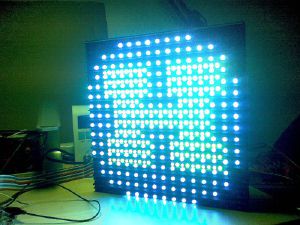
Equipment/Piccadilly circus LED sign
The LED sign is awesome in every way the jumbotron was not: it has high pixel density, brightness, and low weight, AND pretty simple insides.
| LED signs | |
|---|---|
 | |
| Model | Unknown |
| Sub-category | Audio/Visual |
| Consumables | Unknown |
| Accessories | Unknown |
| Training link | Unknown |
| ACnode | no |
| Owner | Unknown |
| Origin | Donation |
This Howto is a basic hack to drive on of the tiles
What is what
The board is made of segments each with four columns and a column has three tiles. Each tile has 16x16 pixels RGB.
In this document we are interested in the tiles as they are the easiest. They can be driven my AVR/Arduinos
Instructional video by Mike Harrison
Pinout
The tiles have the following pinout
 1. FLACK
 2. NC
 3. NC
 4. MA0
 5. MA1
 6. NC
 7. BRIGHTNESS
 8. NC
 9. R_EN
10. G_EN
11. B_EN
12. GND
13. R_DATA
14. GND
15. G_DATA
16. GND
17. B_DATA
18. GND
19. SCLK
20. GND
Inside the module looks like this
Note: The arrangement of the pixels is not a nice linear buffer!
 Top left front pixel
 \/
+--+--+--+--+--+--+--+--+--+--+--+--+--+--+--+--+  +--+--+--+--+--+--+--+--+--+--+--+--+--+--+--+--+
|0f|0e|0d|0c|0b|0a|09|08|07|06|05|04|03|02|01|00|  |1f|1e|1d|1c|1b|1a|19|18|17|16|15|14|13|12|11|10|
+--+--+--+--+--+--+--+--+--+--+--+--+--+--+--+--+  +--+--+--+--+--+--+--+--+--+--+--+--+--+--+--+--+
|00|01|02|03|04|05|06|07|08|09|0a|0b|0c|0d|0e|0f|  |10|11|12|13|14|15|16|17|18|19|1a|1b|1c|1d|1e|1f|
+--+--+--+--+--+--+--+--+--+--+--+--+--+--+--+--+  +--+--+--+--+--+--+--+--+--+--+--+--+--+--+--+--+
|                                                                                                  |
|                                            .  .  .  .                                            |
|                                                                                                  |
+--+--+--+--+--+--+--+--+--+--+--+--+--+--+--+--+  +--+--+--+--+--+--+--+--+--+--+--+--+--+--+--+--+
|cf|ce|cd|cc|cb|ca|c9|c8|c7|c6|c5|c4|c3|c2|c1|c0|  |ef|ee|ed|ec|eb|ea|e9|e8|e7|e6|e5|e4|e3|e2|e1|e0|
+--+--+--+--+--+--+--+--+--+--+--+--+--+--+--+--+  +--+--+--+--+--+--+--+--+--+--+--+--+--+--+--+--+
|d0|d1|d2|d3|d4|d5|d6|d7|d8|d9|da|db|dc|dd|de|df|  |f0|f1|f2|f3|f4|f5|f6|f7|f8|f9|fa|fb|fc|fd|fe|ff|
+--+--+--+--+--+--+--+--+--+--+--+--+--+--+--+--+  +--+--+--+--+--+--+--+--+--+--+--+--+--+--+--+--+
                                                                                                 /\
                                                                            Bottom right front pixel
Writing stuff!
Hook all the pins up and strobe them all high. Basically the FLATCH signals the start of the frame. The R_EN, G_EN, B_EN need to be pulsed high at the start if you want those colours.
Then drop them all low. Now write one bit by placing the data on R_DATA, B_DATA and G_DATA pins with CLOCK high. Then drop the CLOCK. Data is written on the falling edge.
How should it work?
Well this is a hack. Please read the documentation for proper timing diagrams. It is supposed to be driven at 12.5mhz but anything lower shouldn't spook it too much and an ardiuno/avr is not going to get close to that clock frequency.
RGB gradients are accomplished by writing the data fast enough to do PWM.
Things done with the tile so far
- The Imperial College Robotics Society has made a lot of progress, and their code now displays various parametric visualizations, as well as gifs, with good colour mixing.