Project:BinaryClock
From London Hackspace Wiki
(Redirected from Projects/BinaryClock)
What
An extension of the binary clock that Ciarán made after the Arduino Workshop.

Design Criteria
- Must have a nice case.
- Must have a time display (duh).
- Must have a minimum of buttons, preferably two
- Will use GPS time/date to be semi-accurate.
- Must be able to change between GMT/BST
- Must be as low power, long life as possible.
- By default time display will be off.
Non-essentials
- Nice to have a external output, ie when alarm goes off a pin goes high. So alarm can be hacked to trigger other events.
How
Logic
Button Logic
Buttons need to snooze, set alarm, show date, show time, show alarm.
The following is based on two buttons
- Either button will snooze the alarm, if alarm is sounding.
- Holding button 1 will turn alarm off.
- Button 1 will show time (when no time or date is displayed).
- Button 2 will show date.
- Holding button 2 will show alarm.
- Holding Button 1+2 will put clock into set alarm mode.
- Button 1 will increase the hour, button 2 will set the hour.
- Button 1 will increase minute, button 2 will set the minute.
- Clock will go back to displaying the time.
State Logic
| State | Description | Actions |
|---|---|---|
| 1 | Display off. | Click 1 > 6, Click 2 > 5 |
| 2 | Alarm On. | Click 1 or 2 > 3, Hold 1 > 4 |
| 3 | Snoozed | Hold 1 > 4 |
| 4 | Showing Time | Hold 1+2 > 7 |
| 5 | Showing Date | None |
| 6 | Show Alarm | Hold 1+2 > 7 |
| 7 | Set Alarm | Button 1 or 2 |
Display Feedback
Sound Feedback
Code
Get it here! - Note: There is no code yet, really.
Hardware
Laser cutter designs for enclosure.
TODO
- Get accurate time measurement
- Add buttons
- Add ability to set an alarm
- Add a piezo
- Make battery supply
- Make it "radio-controlled"
- Make a box
| Task | Date Completed |
|---|---|
| Prototype Display | |
| Display PCB | |
| Prototype Buttons | |
| PCB Buttons | |
| Prototype Alarm | |
| PCB Alarm | |
| Prototype Time | |
| PCB Time | |
| Prototype Combined Clock | |
| PCB Combined Clock |
Code
Circuit
Rev 1
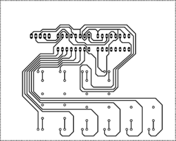
Designed PCB for shift registers, and LEDs. This board will become the "Display"
Rev 2
Gave up trying to design a PCB. Decided to go back to using veroboard. Circuit has been designed on graph a paper
