Project:Sanguinololu Thermocouple: Difference between revisions
No edit summary |
|||
| (56 intermediate revisions by one other user not shown) | |||
| Line 1: | Line 1: | ||
{{Project | {{Project | ||
|name=Sanguinololu Thermocouple | |name=Sanguinololu Thermocouple | ||
|created = 03/11/2012 | |created=03/11/2012 | ||
|version = 1 | |version=1 | ||
|members = [[User:Pinski1|Pinski1]] | |members=[[User:Pinski1|Pinski1]] | ||
|status = Awaiting PCBs | |status=Awaiting PCBs | ||
|qrmode = 1 | |qrmode=1 | ||
}} | }} | ||
I wanted to add a thermocouple to my 3D printer's hot end. Ideally it would improve the quality of my printed objects as it would provide more accurate temperature readings with greater immunity from electronic noise generated by the stepper motors. | I wanted to add a thermocouple to my 3D printer's hot end. Ideally it would improve the quality of my printed objects as it would provide more accurate temperature readings with greater immunity from electronic noise generated by the stepper motors. | ||
== Features == | == Features == | ||
The PCB I have designed has the following features: | The PCB I have designed has the following features: | ||
*Fits onto the expansion headers already present on the Sanguinololu | *Fits onto the expansion headers already present on the Sanguinololu | ||
*Adds a MAX31855 | *Adds a MAX31855 thermocouple to digital convertor chip | ||
*Enables temperature readings between - | *Enables temperature readings between -200°C to +1350°C ±2°C | ||
*Has a resolution of 0. | *Has a resolution of 0.25°C | ||
*Can sample at 10Hz | |||
== Files == | == Files == | ||
=== | === Schematic === | ||
[[File:Sanguinololu_Thermocouple_Schematic.png|500px]] | |||
Eagle 5.11 file | |||
The Eagle 5.11 schematic [https://dl.dropbox.com/u/3638084/Rev%201.sch file]. | |||
=== PCB Layout === | === PCB Layout === | ||
[[File:Sanguinololu_Thermocouple_Layout.png|500px]] | |||
Eagle 5.11 file | |||
=== | The Eagle 5.11 board [https://dl.dropbox.com/u/3638084/Rev%201.brd file]. | ||
=== Bill of Materials === | |||
{| class="wikitable" | |||
!Qty | |||
!Value | |||
!Ident | |||
!Description | |||
|- | |||
|1 | |||
|TXB0104D | |||
|IC1 | |||
|SOIC14 Bi-Directional level translator chip | |||
|- | |||
|1 | |||
|TPS73033DBVT | |||
|IC2 | |||
|Could be any SOT23-5 +3V3 voltage regulator | |||
|- | |||
|1 | |||
|MAX31855KASA+ | |||
|IC3 | |||
|SOIC8 Thermocouple-to-Digital chip | |||
|- | |||
|2 | |||
|2.2uF | |||
|C1, C2 | |||
|Ceramic 1206 decoupling capacitors | |||
|- | |||
|3 | |||
|10nF | |||
|C3, C4, C5 | |||
|Ceramic 0805 decoupling capacitors | |||
|- | |||
|1 | |||
| | |||
|SV1 | |||
|2x5 way, straight, 2.54mm pitch, female header | |||
|- | |||
|1 | |||
| | |||
|X1 | |||
|2way, screw terminal, 5.08mm pitch | |||
|- | |||
|1 | |||
| | |||
| | |||
|Thermocouple, K Type | |||
|} | |||
=== Pictures === | === Pictures === | ||
<!--pictures, including in situ--> | <!--pictures, including in situ--> | ||
{| | |||
!Top | |||
!Bottom | |||
| | |||
|- | |||
|[[File:Sanguinololu_PCB_top_eagle.png]] | |||
|[[File:Sanguinololu_PCB_bottom_eagle.png]] | |||
|The Eagle CAD layout. | |||
|- | |||
|colspan="2"|[[File:Sanguinololu_PCB_Render.png|400px]] | |||
|The Eagle CAD 3D render | |||
|- | |||
|[[File:Sanguinololu_PCB_top.png]] | |||
|[[File:Sanguinololu_PCB_bottom.png]] | |||
|The PCB renders of OSH Park | |||
|- | |||
|[[File:Sanguinololu_PCB_top_manufactured.png]] | |||
|[[File:Sanguinololu_PCB_bottom_manufactured.png]] | |||
|The delivered PCBs. | |||
|- | |||
|colspan="2"|[[File:Sanguinololu_Thermocouple_board_completed.png|400px]] | |||
|The soldered board. | |||
|} | |||
== How to Build == | == How to Build == | ||
Tools required: | |||
*soldering iron | |||
*solder | |||
*tweezers | |||
Tools that would be useful: | |||
*solder sucker | |||
*solder wick | |||
*magnifier | |||
=== Soldering === | |||
#Start by soldering the MAX31855KASA+ into position. Ensure pin 1 is correct and all the pins are lined up. | |||
#Next solder in the TXB0104B, agin ensure pin 1 is correct and the pins line up. | |||
#Solder in the final IC the +3V3 reg. This is the smallest package so special care will need to be taken to ensure the pins like up correctly. | |||
#With the ICs done now solder in the passives. Start with the larger 1206 2.2uF capacitors, these will only fit in two places. | |||
#Then solder in the smaller 0805 10nF capacitors, there should be 3 of these. | |||
#With the surface mount components in place put the 2x5way female header such that it points out the bottom of the board (see the render) and solder it. | |||
#Finally solder in the 2way screw terminals | |||
=== Testing === | |||
You will need a Bus Pirate or something equivalent to communicate with the board and a K type thermocouple to sense the temperature. | |||
== Adding to your 3D printer == | |||
Now the board is complete and tested to work correctly it needs to be fitted to your 3D printer. | |||
=== Attaching to the Sanguinololu === | |||
/images of the board attached/ | |||
[[File:Sanguinololu_Thermocouple_mounted.png|thumb|Sanginololu Thermocouple Rev 1 attached to a Sanguinololu on my [http://wiki.london.hackspace.org.uk/view/Project:Cupcake-o-Matic Cupcake-o-Matic]]] | |||
===Modifying the code=== | |||
As we are replacing an analogue thermistor with a thermocouple-to-digital device we will need to make changes to the code. | |||
I am in the progress of adding the required code to a local branch of Sprinter which I shall then merge with the master branch. | |||
I also hope to do the same thing to Marlin & TeaCup | |||
== Licence == | == Licence == | ||
This design is licensed under [http://creativecommons.org/licenses/by-nc-sa/2.0/uk/ Creative Commons BY-NC-SA] | This design is licensed under [http://creativecommons.org/licenses/by-nc-sa/2.0/uk/ Creative Commons BY-NC-SA] | ||
This design is modified from [http://reprap.org/wiki/Sanguinololu_SD Sanguinololu SD] | This design is modified from [http://reprap.org/wiki/Sanguinololu_SD Sanguinololu SD] | ||
[[Categories: PCB making]] | |||
Latest revision as of 08:40, 13 April 2017
| [[|Sanguinololu Thermocouple]] | |
|---|---|
| Created | 03/11/2012 |
| Version | 1 |
| Members | Pinski1 |
| Project Status | Awaiting PCBs |
| QR code | |
I wanted to add a thermocouple to my 3D printer's hot end. Ideally it would improve the quality of my printed objects as it would provide more accurate temperature readings with greater immunity from electronic noise generated by the stepper motors.
Features
The PCB I have designed has the following features:
- Fits onto the expansion headers already present on the Sanguinololu
- Adds a MAX31855 thermocouple to digital convertor chip
- Enables temperature readings between -200°C to +1350°C ±2°C
- Has a resolution of 0.25°C
- Can sample at 10Hz
Files
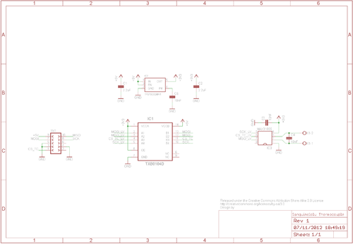
Schematic
The Eagle 5.11 schematic file.
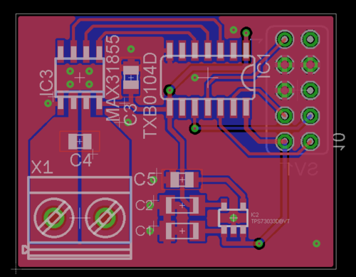
PCB Layout
The Eagle 5.11 board file.
Bill of Materials
| Qty | Value | Ident | Description |
|---|---|---|---|
| 1 | TXB0104D | IC1 | SOIC14 Bi-Directional level translator chip |
| 1 | TPS73033DBVT | IC2 | Could be any SOT23-5 +3V3 voltage regulator |
| 1 | MAX31855KASA+ | IC3 | SOIC8 Thermocouple-to-Digital chip |
| 2 | 2.2uF | C1, C2 | Ceramic 1206 decoupling capacitors |
| 3 | 10nF | C3, C4, C5 | Ceramic 0805 decoupling capacitors |
| 1 | SV1 | 2x5 way, straight, 2.54mm pitch, female header | |
| 1 | X1 | 2way, screw terminal, 5.08mm pitch | |
| 1 | Thermocouple, K Type |
Pictures
| Top | Bottom | |
|---|---|---|
|
|
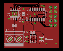
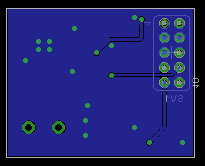
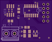
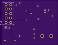
The Eagle CAD layout. |
|
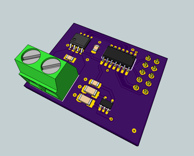
The Eagle CAD 3D render | |
|
|
The PCB renders of OSH Park |
|
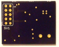
|
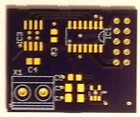
The delivered PCBs. |
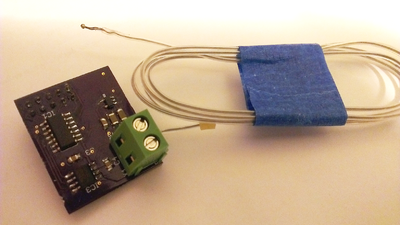
|
The soldered board. | |
How to Build
Tools required:
- soldering iron
- solder
- tweezers
Tools that would be useful:
- solder sucker
- solder wick
- magnifier
Soldering
- Start by soldering the MAX31855KASA+ into position. Ensure pin 1 is correct and all the pins are lined up.
- Next solder in the TXB0104B, agin ensure pin 1 is correct and the pins line up.
- Solder in the final IC the +3V3 reg. This is the smallest package so special care will need to be taken to ensure the pins like up correctly.
- With the ICs done now solder in the passives. Start with the larger 1206 2.2uF capacitors, these will only fit in two places.
- Then solder in the smaller 0805 10nF capacitors, there should be 3 of these.
- With the surface mount components in place put the 2x5way female header such that it points out the bottom of the board (see the render) and solder it.
- Finally solder in the 2way screw terminals
Testing
You will need a Bus Pirate or something equivalent to communicate with the board and a K type thermocouple to sense the temperature.
Adding to your 3D printer
Now the board is complete and tested to work correctly it needs to be fitted to your 3D printer.
Attaching to the Sanguinololu
/images of the board attached/
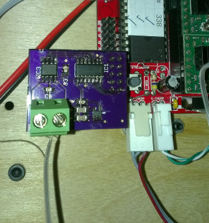
Modifying the code
As we are replacing an analogue thermistor with a thermocouple-to-digital device we will need to make changes to the code.
I am in the progress of adding the required code to a local branch of Sprinter which I shall then merge with the master branch.
I also hope to do the same thing to Marlin & TeaCup
Licence
This design is licensed under Creative Commons BY-NC-SA
This design is modified from Sanguinololu SD
