Equipment/Britannia Lathe: Difference between revisions
mNo edit summary |
Deanforbes (talk | contribs) (machine was retired as pert conversation on mailing list) |
||
| (13 intermediate revisions by 4 users not shown) | |||
| Line 1: | Line 1: | ||
{{EquipmentInfobox | {{EquipmentInfobox | ||
| name = Britannia lathe <!-- Name of the item. --> | |name=Britannia lathe <!-- Name of the item. --> | ||
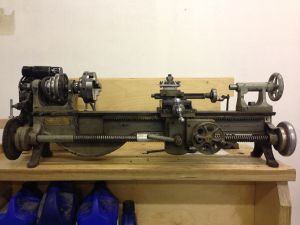
| image = | |image=Britannia_lathe.jpg<!-- Image of the item. Leave with placeholder image if none exists. --> | ||
| model = Unknown <!-- Model --> | |model=Unknown <!-- Model --> | ||
| category = Equipment <!-- Main category. Please leave alone to keep item in this category --> | |category=Equipment <!-- Main category. Please leave alone to keep item in this category --> | ||
| subcat = | |subcat=Defunct | ||
| status = | |status=Scrapped | ||
| consumables = Unknown <!-- Any items used up in normal operation, such as; ink, paper, saw-blades, cutting disks, oil, etc.. --> | |consumables=Unknown <!-- Any items used up in normal operation, such as; ink, paper, saw-blades, cutting disks, oil, etc.. --> | ||
| accessories = Unknown <!-- Any items associated with the equipment but not consumable, such as; drill bits, safety gloves, goggles, etc.. --> | |accessories=Unknown <!-- Any items associated with the equipment but not consumable, such as; drill bits, safety gloves, goggles, etc.. --> | ||
| reqtraining = Yes <!-- Is training required to use this equipment? Yes or no. --> | |reqtraining=Yes <!-- Is training required to use this equipment? Yes or no. --> | ||
| trainlink = Unknown <!-- If training is required, provide a link to training signup or contact page. Otherwise leave blank. --> | |trainlink=Unknown <!-- If training is required, provide a link to training signup or contact page. Otherwise leave blank. --> | ||
| acnode = | |acnode=no | ||
| owner = Unknown <!-- Provide a link to owners members page if other than LHS --> | |owner=Unknown <!-- Provide a link to owners members page if other than LHS --> | ||
| origin = Donation<!-- If via pledge, please link to the completed pledge page on the wiki --> | |origin=Donation<!-- If via pledge, please link to the completed pledge page on the wiki --> | ||
| location = <!-- Floor, room/zone and location within that area --> | |location=Basement, main workshop area<!-- Floor, room/zone and location within that area --> | ||
| maintainers = <!-- NO LINKS PLEASE; it currently breaks the template. If someone is nominated as managing the upkeep of this item, please list them here. --> | |maintainers=Oliver <!-- NO LINKS PLEASE; it currently breaks the template. If someone is nominated as managing the upkeep of this item, please list them here. --> | ||
| template_ver = 1.1 <!-- Please do not change. Used for tracking out-of-date templates --> | |template_ver=1.1 <!-- Please do not change. Used for tracking out-of-date templates --> | ||
}} | }} | ||
== Britannia lathe renovation == | == Britannia lathe renovation == | ||
16/4/2014 | |||
It's working. more or less. Needs an ACnode and power switch then we can start training people. there will need to be some adjustments made no doubt, but that has to wait until it can be turned on and off safely. | |||
25/8/2013 | |||
I have found a step pully with a 5/8" bore. This has been fitted to the motor | |||
I have also started construction of a motor mount which will allow releasing tension on the belt to change gear... its a little ugly though, seems I have forgotten how to weld. Will soon be in a position to power it up and turn some stuff! lots that still needs to be done though: | |||
*make finger guard for gears/belt | |||
*rebuild teeth on damaged gears | |||
*build tool to correctly tension the bearings | |||
*get a nice big on off switch and saftey switch | |||
*get an AC node (to protect the machine as much as anything) | |||
27/6/2013 | |||
motor spindle diameter is 5/8" | |||
15/6/2013 | |||
Cleaned rust and grime off ways. Dissassembled entire carriage, cross slide, compound slide and cleaned througherly. (Mostly) put back together. Motion much smoother now in main area, though travel still stiff at tailstock end, not too worried about that as no one will be cutting anything down there anyway I suspect. Its better than it was anyway. | |||
At some point someone has added a gearbox to the rack & pinion, which is great expect that it gets in the way of one of the bolts that holds the saddle to the apron. If you want to take the whole thing apart, you will have to take the gear box off. there are 2 more countersunk screws behind the large gear, which is held in place by a pin (tap it out) and a whole damn lot of friction (WD40 and lots of leavering) | |||
Artag has kindly donated a step pulley which has aproximatly the correct dimensions, the bore needs enlarging though which means I (or someone) need access to the 3 in 1. trying to do this on the pillar drill would probably make it wobbly. | |||
12/6/2013 | |||
Step pully dimensions: | |||
small: 33.8mm | |||
med: 54.8mm | |||
large: 72.4mm | |||
8/6/2012 | |||
Roughly fitted a dust cover that folds over behind the cabinet when not in use. Will neaten it up when its all bolted down and finger guards etc are in place. | |||
Removed, dissassembeled and cleaned headstock. | |||
The spindle bearings are just the steel spindle on the cast iron casting and are tapered such that the effects of wear can be mitigated by tightening the bearing at the rear end, which draws both spindle bearings tighter into the casting bearing. There is a ball raced thrust bearing on the chuck end so pressure on the chuck does not force the taper of the bearing into the casting too tightly and damage it. This will all have to be carefully adjusted and locked in position before proper operation. | |||
The rear end of the spindle has suffered some calamity at some point previously which someone has repaired by addition of an adapter part, however there is not much metal left in the linkage between the spindle and the lead screw driving gears. For this reason any serious load on the leadscrew is likely to chew off the end of the spindle entirely. | |||
Options for spindle repair: | |||
a) Leave it alone until it breaks totally | |||
b) Make custom gear-spindle adapter. re-machine broken end to accept a custom made adapter. braze them both together. (forget welding, brazeing would be hard enough to do accuratly) | |||
c) Machine new spindle. (damn hard, its a considerable bit of engineering even by todays standards) | |||
d) Drive leadscrew from something else. somehow. | |||
Ran out of time today and left it with the leadscrew driving assembly in bits in a tray on the lathe cabinet. Its all covered by the dust cover so should be ok until next weekend. | |||
1/6/2013 | |||
Did some more work on the motor table, It now bolts onto the bench with some bits of studding. When the motor is finalized, i'll cut some bits of scaffold tube for spacers to get it to the right height. | |||
Need to acquire an ACnode for it. Also need a step pully. | |||
27/5/2013 Removed tool board from back board. it's stored under/behind the lathe cabinet. Cut bit of wood for the motor to sit on. it's sitting in place for now with a sign not to remove. Will fasten it in place permanently when final motor decision is made. | 27/5/2013 Removed tool board from back board. it's stored under/behind the lathe cabinet. Cut bit of wood for the motor to sit on. it's sitting in place for now with a sign not to remove. Will fasten it in place permanently when final motor decision is made. | ||
There is a potential 12VDC in my box, will need to make a speed controller for it. Alternatively just use a normal mains motor with a step pully as the lathe was designed for. 3 phase motors with inverter speed controllers start to look expensive. | There is a potential 12VDC in my box, will need to make a speed controller for it. Alternatively just use a normal mains motor with a step pully as the lathe was designed for. 3 phase motors with inverter speed controllers start to look expensive. | ||
-Oliver | |||
== Pictures == | |||
{| | |||
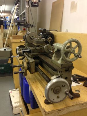
| [[File:Britannia_lathe_tailstock.jpg|thumb|The lathe, seen from the tailstock end]] | |||
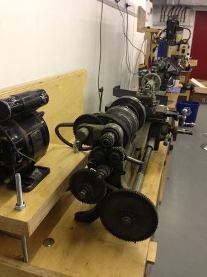
| [[File:Britannia_lathe_chuck.jpg|thumb|The lathe, seen from the chuck end]] | |||
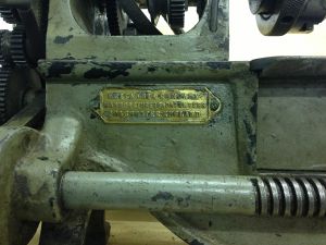
| [[File:Britannia_lathe_nameplate.jpg|thumb|The lathe's nameplate.]] | |||
|} | |||
Latest revision as of 20:59, 15 August 2015
Britannia lathe renovation
16/4/2014 It's working. more or less. Needs an ACnode and power switch then we can start training people. there will need to be some adjustments made no doubt, but that has to wait until it can be turned on and off safely.
25/8/2013 I have found a step pully with a 5/8" bore. This has been fitted to the motor I have also started construction of a motor mount which will allow releasing tension on the belt to change gear... its a little ugly though, seems I have forgotten how to weld. Will soon be in a position to power it up and turn some stuff! lots that still needs to be done though:
- make finger guard for gears/belt
- rebuild teeth on damaged gears
- build tool to correctly tension the bearings
- get a nice big on off switch and saftey switch
- get an AC node (to protect the machine as much as anything)
27/6/2013 motor spindle diameter is 5/8"
15/6/2013
Cleaned rust and grime off ways. Dissassembled entire carriage, cross slide, compound slide and cleaned througherly. (Mostly) put back together. Motion much smoother now in main area, though travel still stiff at tailstock end, not too worried about that as no one will be cutting anything down there anyway I suspect. Its better than it was anyway.
At some point someone has added a gearbox to the rack & pinion, which is great expect that it gets in the way of one of the bolts that holds the saddle to the apron. If you want to take the whole thing apart, you will have to take the gear box off. there are 2 more countersunk screws behind the large gear, which is held in place by a pin (tap it out) and a whole damn lot of friction (WD40 and lots of leavering)
Artag has kindly donated a step pulley which has aproximatly the correct dimensions, the bore needs enlarging though which means I (or someone) need access to the 3 in 1. trying to do this on the pillar drill would probably make it wobbly.
12/6/2013 Step pully dimensions:
small: 33.8mm med: 54.8mm large: 72.4mm
8/6/2012 Roughly fitted a dust cover that folds over behind the cabinet when not in use. Will neaten it up when its all bolted down and finger guards etc are in place.
Removed, dissassembeled and cleaned headstock. The spindle bearings are just the steel spindle on the cast iron casting and are tapered such that the effects of wear can be mitigated by tightening the bearing at the rear end, which draws both spindle bearings tighter into the casting bearing. There is a ball raced thrust bearing on the chuck end so pressure on the chuck does not force the taper of the bearing into the casting too tightly and damage it. This will all have to be carefully adjusted and locked in position before proper operation.
The rear end of the spindle has suffered some calamity at some point previously which someone has repaired by addition of an adapter part, however there is not much metal left in the linkage between the spindle and the lead screw driving gears. For this reason any serious load on the leadscrew is likely to chew off the end of the spindle entirely. Options for spindle repair: a) Leave it alone until it breaks totally b) Make custom gear-spindle adapter. re-machine broken end to accept a custom made adapter. braze them both together. (forget welding, brazeing would be hard enough to do accuratly) c) Machine new spindle. (damn hard, its a considerable bit of engineering even by todays standards) d) Drive leadscrew from something else. somehow.
Ran out of time today and left it with the leadscrew driving assembly in bits in a tray on the lathe cabinet. Its all covered by the dust cover so should be ok until next weekend.
1/6/2013
Did some more work on the motor table, It now bolts onto the bench with some bits of studding. When the motor is finalized, i'll cut some bits of scaffold tube for spacers to get it to the right height.
Need to acquire an ACnode for it. Also need a step pully.
27/5/2013 Removed tool board from back board. it's stored under/behind the lathe cabinet. Cut bit of wood for the motor to sit on. it's sitting in place for now with a sign not to remove. Will fasten it in place permanently when final motor decision is made.
There is a potential 12VDC in my box, will need to make a speed controller for it. Alternatively just use a normal mains motor with a step pully as the lathe was designed for. 3 phase motors with inverter speed controllers start to look expensive. -Oliver


