Equipment/Britannia Lathe: Difference between revisions
No edit summary |
|||
| Line 20: | Line 20: | ||
8/6/2012 | 8/6/2012 | ||
Roughly fitted a dust cover that folds over behind the cabinet when not in use. | Roughly fitted a dust cover that folds over behind the cabinet when not in use. Will neaten it up when its all bolted down and finger guards etc are in place. | ||
Removed, dissassembeled and cleaned headstock. | Removed, dissassembeled and cleaned headstock. | ||
Revision as of 20:25, 8 June 2013
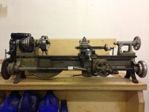
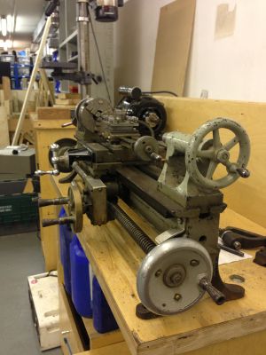
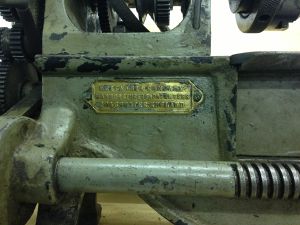
Britannia lathe renovation
8/6/2012 Roughly fitted a dust cover that folds over behind the cabinet when not in use. Will neaten it up when its all bolted down and finger guards etc are in place.
Removed, dissassembeled and cleaned headstock. The spindle bearings are just the steel spindle on the cast iron casting and are tapered such that the effects of wear can be mitigated by tightening the bearing at the rear end, which draws both spindle bearings tighter into the casting bearing. There is a ball raced thrust bearing on the chuck end so pressure on the chuck does not force the taper of the bearing into the casting too tightly and damage it. This will all have to be carefully adjusted and locked in position before proper operation.
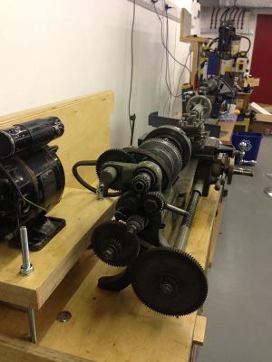
The rear end of the spindle has suffered some calamity at some point previously which someone has repaired by addition of an adapter part, however there is not much metal left in the linkage between the spindle and the lead screw driving gears. For this reason any serious load on the leadscrew is likely to chew off the end of the spindle entirely. Options for spindle repair: a) Leave it alone until it breaks totally b) Make custom gear-spindle adapter. re-machine broken end to accept a custom made adapter. braze them both together. (forget welding, brazeing would be hard enough to do accuratly) c) Machine new spindle. (damn hard, its a considerable bit of engineering even by todays standards) d) Drive leadscrew from something else. somehow.
Ran out of time today and left it with the leadscrew driving assembly in bits in a tray on the lathe cabinet. Its all covered by the dust cover so should be ok until next weekend.
1/6/2013
Did some more work on the motor table, It now bolts onto the bench with some bits of studding. When the motor is finalized, i'll cut some bits of scaffold tube for spacers to get it to the right height.
Need to acquire an ACnode for it. Also need a step pully.
27/5/2013 Removed tool board from back board. it's stored under/behind the lathe cabinet. Cut bit of wood for the motor to sit on. it's sitting in place for now with a sign not to remove. Will fasten it in place permanently when final motor decision is made.
There is a potential 12VDC in my box, will need to make a speed controller for it. Alternatively just use a normal mains motor with a step pully as the lathe was designed for. 3 phase motors with inverter speed controllers start to look expensive. -Oliver


