Equipment/Stratasys FDM 1650: Difference between revisions
(→TODO) |
|||
| Line 27: | Line 27: | ||
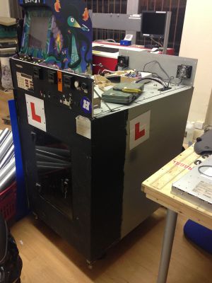
| [[File:Stratasys_side.jpg|thumb|A side view of the Stratasys.]] | | [[File:Stratasys_side.jpg|thumb|A side view of the Stratasys.]] | ||
|} | |} | ||
=Specification & documentation= | =Specification & documentation= | ||
Revision as of 16:46, 16 March 2015
| Stratasys 3D printer | |
|---|---|
 | |
| Sub-category | CNC |
| Status | Under construction |
| Consumables | Printer filament |
| Training requirement | Yes |
| Training link | #Training & instruction |
| ACnode | no |
| Owner | LHS |
| Origin | Donation |
| Location | 3D printer area, Ground floor |
| Maintainers | Hipster |
Description
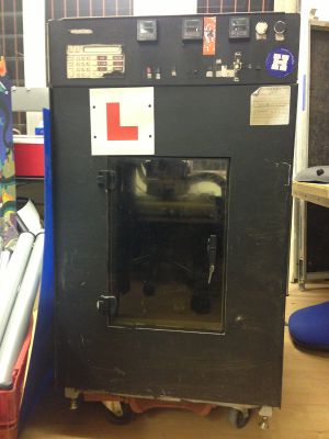
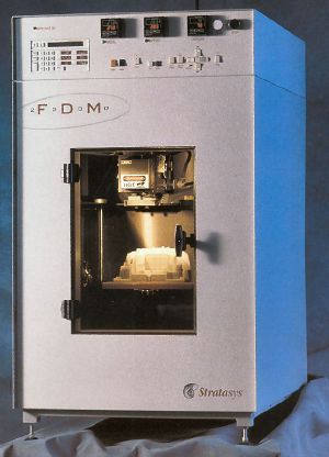
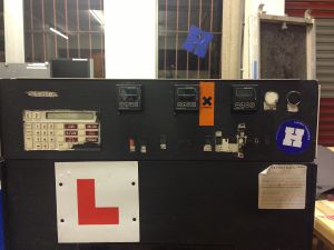
The Stratasys is a commercial-grade 3D printer that was donated to the LHS by Imperial College London. It was repaired for a time, but is currently undergoing an extensive refurbishment to bring the electronics up to modern standards and properly convert it to non-vendor-specific feedstock.
Pictures
Specification & documentation
As the Stratasys is undergoing extensive modification to it's control electronics, material use requirements and printheads, the factory specifications and original instructions for use are unlikely to remain accurate once refurbishment is complete. The previous specifications and instructions will likely be updated at that time.
Broadly, the only things likely to remain the same is the large 11x11x11inch printing volume, the dual-head extruder setup, controlled printing enclosure, and high-resolution industrial mechanics.
Original docs
UK reseller is http://www.laserlines.co.uk/. This one may have come direct from Stratasys, though.
- Extensive blog on the 1650 and 2000
- Manuals for an FDM 2000 (includes description of Quickslice 5.0 - 1997):
- Page referencing these and C:\QuickSliceV64-qsni
- Calibration file
- Webcams
- Another 1650 owner
- Repairing an FDM 2000
- Insight User guide (2005)
- Stratasys product page (1999)
- Philadelphia hackspace with an FDM 2000
Training & instruction
For pre-refurbishment instructions & settings, see the legacy sub-page here: Stratasys_FDM_1650/Legacy#Training_.26_instruction
Consumables
Only filament provided by the maintainers can be used in the Lulzbot. This is to prevent any issues with poor quality filament. If we're running low on filament (or tape), ro recommended alternative providers, let them know (via the mailing list).
Filament options (3.0mm)
- ABS (lego brick plastic - prints at 190-230 DegC, requires heated bed at 100-110 DegC)
- PLA (biodegradable , based on food starch - prints at 185-190 DegC, optional heated bed, not hotter than 60 DegC)
- There are other 'specialist' filament, like wood effect, stone effect, nylon (can be coloured by clothes dye), etc
Log
Original use
For pre-refurbishment logs, see the legacy sub-page here: Stratasys_FDM_1650/Legacy#Logs
Refurbishment
TODO
- 1.
Remove all the unnecessary wiring, including the old heater tubes.16-05-2013 - 2.
Identify the wiring on the steppers (these are wired differently to normal).16-05-2013 - 3.
Connect the motors to the 4pi (http://wiki.arcol.hu/blog:4pi) and calibrate the settings. - 4.
Redesign the head end for 2 hot-ends and extruders. - 5.
Connected hot ends and run heat and thermistor checks. - 6.
Head end redesign complete, waiting for aluminium part for mounting hot-ends - 7.
Filament path checks. - 8. Install Raspberry Pi with Octoprint and touch-screen.
- 9. Dual head calibration test print.
- 10. Heated chamber (required for ABS), phase 2.
Updates
1-6-2014
After providing spare hands to tgreer in trying to get the new controller wired in for the open-day, I noticed both motor connector plastics are extremely perished. Sockets and plugs. The Y-axis (?) stepper connector has previously been bodged. Pins no longer make good electrical contact with bodged SIL connector. This is both due to bent pins that have apparently been forced, but also the SIL socket terminals sliding freely in their plastics. Pins on stepper are also able to move into the motor body when pressed! Attempting to press another connector onto them will likely push them all the way into the motor housing, rendering the motor useless. As the motor pins still pass continuity tests, this severely damaged connection seems the likely reason for the motor skipping phases. My recomendation is that flying leads are soldered directly to the damaged pins and connected to a seperate connector that can be fixed to the chassis. Possibly a DB9. Replacing the steppers entirely is a possibility, but will be tricky due to the capstan-drive. Removing the stepper will probably mean re-winding and re-tensioning the system.
The capstan drums seem at risk already however, as the (nylon?) coating on the steel cable is severely deteriorated, cracked and flaking off. Once the coating fails sufficiently to expose the cable, the cable will begin to eat into the surface of the aluminium capstan drums, ruining them. The drums are not likely to be easily replaced, the motors and cable are.
While the cable is fine for testing use, if the Statasys is going to be used frequently, new cable should be sourced as a priority.
- Sci
27-11-2013
The milled parts should arrive any day now and, once installed, we should be ready for a first test print.
As far as I am concerned, based on the investment by members, a successful print of any description, using both extruders or not, is proof of working. Having experimented with Dual Extruders, the configuration too complicated to include this by the (self imposed) deadline.
Thanks Ian
01-11-2013
Currently the Stratasys is moving and the hot-ends/extruders are working. We are waiting for the aluminium to mount the hot-ends in.
Once this is completed, it shouldn't take much longer to have this completed and working.
However, as I mentioned on IRC, if we cannot have a completed print by Christmas, I think this project should be marked as 'not completable' (if there is such as word) and we call it a day...
Thanks Ian
16-05-2013
To the mailing list:
Hey all.
Right, finally got time today to do a thorough check-up on the stratasys. As I have rpreviously said, all internal mechanics (including the steppers) are in full working order, especially as I performed a strip and clean to it pre-move.
After a quick talk with Ian on Wednesday, I have traced all the cables and found all the documentation for the parts, ferrous detecting end-stops, x-y controller pin outs, steppers etc. I have removed the old and power hungry heaters and flourescent lights.
I have paird the stepper cables and made ready for the 4-wire board. Also gave another clean
Basically it is ready to be connected to control board and ready to run.
All we need now are to nice tourqey nema17 steppers, 2 j-hotends (ian has offered to source and will start pledge, less than £100). Once these have turned up and I've cad modeled them, i will design a nice clean and easily accesable mount for them in the existing hot end housing (also been cleaned).
Charles will need to add a ACNode and it'll be up and running as a tool for the space. But like the laser cutter and charles, I will be its main care-taker/daddy lol.
Hope this has cleared up any concerns or apprensions about having a fully working, accurate, industrial 3D printer in the space to be used by people with training.
Regards
Hipster
Links
Training
- A course on this machine
Modification
- Lengthy description of the print process (for automation)
- Modification for makerbot-style self-supporting objects
- Using makerbot parts


