Equipment/Staubli/J11
From London Hackspace Wiki
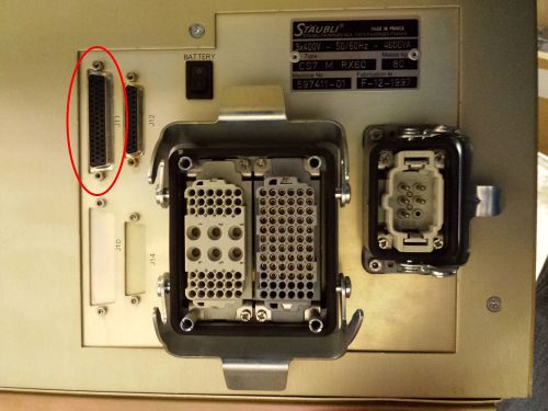
The J11 connector on the back of the Staubli controller contains the digital IO lines.
There are 6 relay outputs and 12 digital inputs. The connector can also supply 24v power.
Outputs 7 & 8 are used in the arm to control the gripper solenoids.
The connector has 50 pins, in three rows. Refer to the following manuals for details and schematics :
- Page 9 – CS7 Electrical Diagrams
- Page 50 – CS7 User Guide
| Pin# | Description |
|---|---|
| 1 | O1+ (Output 1 relay contacts) |
| 2 | O1- (Output 1 relay contacts) |
| 3 | O2+ (Output 2 relay contacts) |
| 4 | O2- (Output 2 relay contacts) |
| 5 | O3+ (Output 3 relay contacts) |
| 6 | O3- (Output 3 relay contacts) |
| 7 | O4+ (Output 4 relay contacts) |
| 8 | O4- (Output 4 relay contacts) |
| 9 | O5+ (Output 5 relay contacts) |
| 10 | O5- (Output 5 relay contacts) |
| 11 | O6+ (Output 6 relay contacts) |
| 12 | O6- (Output 6 relay contacts) |

