Equipment/Staubli/J11
From London Hackspace Wiki
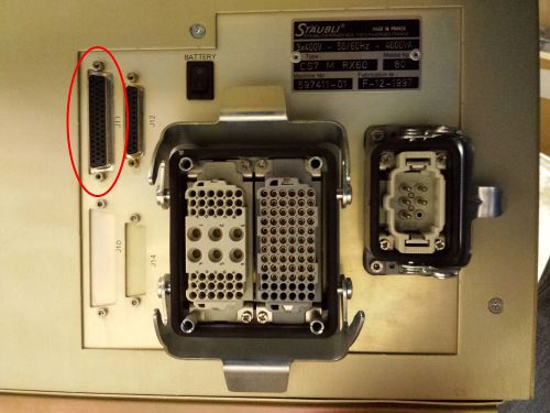
The J11 connector on the back of the Staubli controller contains the digital IO lines.
There are 6 relay outputs and 12 digital inputs. The connector can also supply 24v power.
The outputs are isolated normally open relay contacts, maximum rating at 125v @ 1A. Outputs 7 & 8 are used in the arm to control the gripper solenoids.
The inputs are opto-isolation 24v LED inputs. LOW = 0v-3v. HIGH = 10-24v. As they are LED opto-isolators, they only work with the correct polarity.
The outputs can be activated and deactivated in V+ like this :
SIGNAL 1                  // turns relay output 1 on
SIGNAL -1                 // turns relay output 1 off
SIGNAL 1,2,3,4,5,6        // turns relays 1-6 all on
SIGNAL -1,-2,-3,-4,-5,-6  // turns relays 1-6 all off
The inputs are used in V+ like this :
WAIT SIG(1001) // this pauses the V+ program until input 1 is activated and then continues.
The connector has 50 pins, in three rows. Refer to the following manuals for details and schematics :
- Page 9 – CS7 Electrical Diagrams
- Page 50 – CS7 User Guide
| Pin# | Description |
|---|---|
| 1 | O1+ (Output 1 relay contacts) |
| 2 | O1- (Output 1 relay contacts) |
| 3 | O2+ (Output 2 relay contacts) |
| 4 | O2- (Output 2 relay contacts) |
| 5 | O3+ (Output 3 relay contacts) |
| 6 | O3- (Output 3 relay contacts) |
| 7 | O4+ (Output 4 relay contacts) |
| 8 | O4- (Output 4 relay contacts) |
| 9 | O5+ (Output 5 relay contacts) |
| 10 | O5- (Output 5 relay contacts) |
| 11 | O6+ (Output 6 relay contacts) |
| 12 | O6- (Output 6 relay contacts) |
| 13 | I1+ (Input 1 positive) |
| 14 | I1- (Input 1 negative) |
| 15 | I2+ (Input 2 positive) |
| 16 | I2- (Input 2 negative) |
| 17 | I3+ (Input 3 positive) |
| 18 | I3- (Input 3 negative) |
| 19 | I4+ (Input 4 positive) |
| 20 | I4- (Input 4 negative) |
| 21 | I5+ (Input 5 positive) |
| 22 | I5- (Input 5 negative) |
| 23 | I6+ (Input 6 positive) |
| 24 | I6- (Input 6 negative) |
| 25 | I7+ (Input 7 positive) |
| 26 | I7- (Input 7 negative) |
| 27 | I8+ (Input 8 positive) |
| 28 | I8- (Input 8 negative) |
| 29 | I9+ (Input 9 positive) |
| 30 | I9- (Input 9 negative) |
| 31 | I10+ (Input 10 positive) |
| 32 | I10- (Input 10 negative) |
| 33 | I11+ (Input 11 positive) |
| 34 | I11- (Input 11 negative) |
| 35 | I12+ (Input 12 positive) |
| 36 | I12- (Input 12 negative) |
| 37 | NC / unknown |
| 38 | NC / unknown |
| 39 | NC / unknown |
| 40 | NC / unknown |
| 41 | NC / unknown |
| 42 | NC / unknown |
| 43 | 24v power |
| 44 | 24v power |
| 45 | NC / unknown |
| 46 | NC / unknown |
| 47 | NC / unknown |
| 48 | NC / unknown |
| 49 | NC / unknown |
| 50 | NC / unknown |
| Shell / Shield | Ground |

