Difference between revisions of "Project:Nanode/docs"
(Added table of Pin connections) |
|||
| Line 10: | Line 10: | ||
[[File:Nanode_conns.jpg|500px]] as JPG | [[File:Nanode_conns.jpg|500px]] as JPG | ||
| − | {| | + | {| border="1" cellspacing="0" cellpadding="4" |
| − | |||
|- | |- | ||
| − | ! | + | ! Pin !! Description |
| + | |- | ||
| + | | dig0 || Serial RX | ||
| + | |- | ||
| + | | dig1 || Serial TX | ||
| + | |- | ||
| + | | dig2 || - | ||
| + | |- | ||
| + | | dig3 || - | ||
| + | |- | ||
| + | | dig4 || - | ||
| + | |- | ||
| + | | dig5 || - | ||
| + | |- | ||
| + | | dig6 || Red LED | ||
| + | |- | ||
| + | | dig7 || - | ||
| + | |- | ||
| + | | dig8 || SPI: Ethernet Slave Select | ||
| + | |- | ||
| + | | dig9 || - | ||
| + | |- | ||
| + | | dig10 || SPI: Shield Slave Select | ||
| + | |- | ||
| + | | dig11 || SPI: MOSI (Master Output, Slave Input) | ||
| + | |- | ||
| + | | dig12 || SPI: MISO (Master Input, Slave Output) | ||
| + | |- | ||
| + | | dig13 || SPI: Serial Clock (output from master) | ||
|} | |} | ||
Revision as of 22:29, 6 October 2011
Nanode Version 5 Schematic
Nanode Version 5 Schematic as PDF
Nanode Version 5 on Thingiverse
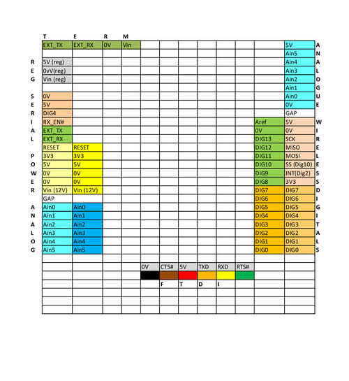
Nanode Version 5 Connections
File:Nanode Connections.pdf as PDF
 as JPG
| Pin | Description |
|---|---|
| dig0 | Serial RX |
| dig1 | Serial TX |
| dig2 | - |
| dig3 | - |
| dig4 | - |
| dig5 | - |
| dig6 | Red LED |
| dig7 | - |
| dig8 | SPI: Ethernet Slave Select |
| dig9 | - |
| dig10 | SPI: Shield Slave Select |
| dig11 | SPI: MOSI (Master Output, Slave Input) |
| dig12 | SPI: MISO (Master Input, Slave Output) |
| dig13 | SPI: Serial Clock (output from master) |
Nanode Version 5 Partslist
Nanode V5 Parts List July 9th 2011
1 Microchip ENC28J60-I/SP 28 PIN 0.3" DIL
1 Microchip 23K256 32Kx8 SPI SRAM SOIC - optional - not supplied in N5 kit
1 EEPROM 2K bit 256x8 SOT23 MAC IC
1 Microchip MCP1702 3V3 regulator TO92 pack
1 7805 5V regulator TO220
1 74HC125 quad tristate buffer
1 Atmel ATmega328-PU
1 1N4001 diode
1 3mm LED RED
2 BZX55C 3V6 500mW zener diodes
1 16MHz HC49-4 crystal 50ppm 30pF load capacitance
1 25MHz HC49-4 crystal 50ppm 30pF load capacitance
4 22pF 50V 10% ceramic disc capacitors 2.54mm pitch
7 100nF 50V 20% multilayer ceramic capacitors Y5V 2.54mm pitch
2 10nF 50V 20% ceramic capacitors 2.54mm pitch
3 10uF 35V electrolytic capacitors 5mm dia 2mm pitch
1 1 ohm resistor (replaces ferrite)
1 10 ohm resistor
4 51 ohm 1% resistors
2 68 ohm 1% resistors
3 270 ohm 1% resistors
1 1K5 1% Resistor
1 2K 1% resistor
5 10K 1% resistors
1 1M Resistor
1 Tactile switch - right angle DTSA-63K
2 8 way 0.1" SIL Sockets
2 6 way 0.1" SIL Sockets
1 6 way 0.1" right angle header
1 32 pin 0.1" header strips
2 28 way DIL sockets
1 14 way DIL socket
1 4 way screw terminal block 20A 5mm (21-3006)
1 USB B connector (24-0346)
1 Ethernet Connector with LEDS (Magjack) 4uCon 19154
1 Pink antistatic zip bag 102 x 156 mm
1 50mm x 50mm conductive foam
1 Mailing Envelope 150 x 210 mm
1 Nanode 5 PCB EPCB100105
Mass 58 grammes Mass 71 grammes when packed in mailing envelope
You will also need
1 FTDI USB-serial cable - becoming a standard bit of kit for talking to microcontrollers or similar USB to serial converter such as Sparkfun/Cool Components 1 CAT5 network cable to connect to router