Difference between revisions of "Project:Robot arm USB control"
(Very brief overview) |
(Added images and more description about the arm itself) |
||
| Line 1: | Line 1: | ||
| − | == | + | __NOEDITSECTION__{{Project|name=Robot arm USB controller|members=[[User:dmi|DMI]]|created=2011-04-12|status=Complete}} |
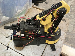
| + | [[File:Robot-arm-kit.jpg|320px|thumb|right|The robot arm]] | ||
I was lucky enough to receive a [http://www.thinkgeek.com/geektoys/science/b696/ robot arm] for Christmas 2010, and it started out with a purely physical controller. After putting the kit together, I found that the physical controller was a little difficult to work with, and a tad unreliable. One of my first thoughts was to make it electrically controlled, preferably by computer via USB. | I was lucky enough to receive a [http://www.thinkgeek.com/geektoys/science/b696/ robot arm] for Christmas 2010, and it started out with a purely physical controller. After putting the kit together, I found that the physical controller was a little difficult to work with, and a tad unreliable. One of my first thoughts was to make it electrically controlled, preferably by computer via USB. | ||
| + | |||
| + | == The arm == | ||
| + | |||
| + | The arm itself has five motors: one in the base for rotation, three joints in the arm, and one used for opening and closing the gripper. There is also an LED in the gripper, to help with targeting. | ||
== Components == | == Components == | ||
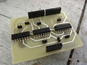
| + | [[File:Robot-arm-controller-pcb-top.jpg|thumb|right|Arduino shield, top]][[File:Robot-arm-controller-pcb-bottom.jpg|thumb|right|Arduino shield, bottom]] | ||
I considered controlling the motors directly with transistors, but soon abandoned that idea on discovering the [http://focus.ti.com/lit/ds/symlink/sn754410.pdf L293D] quadruple half-[http://en.wikipedia.org/wiki/H_bridge H bridge] driver. This provides an easy way of managing the motors' directions by changing the inputs. | I considered controlling the motors directly with transistors, but soon abandoned that idea on discovering the [http://focus.ti.com/lit/ds/symlink/sn754410.pdf L293D] quadruple half-[http://en.wikipedia.org/wiki/H_bridge H bridge] driver. This provides an easy way of managing the motors' directions by changing the inputs. | ||
The circuit simply requires three of these drivers (each one can drive two motors), and power input. | The circuit simply requires three of these drivers (each one can drive two motors), and power input. | ||
Latest revision as of 07:09, 13 April 2011
| Robot arm USB controller | |
|---|---|
| Created | 2011-04-12 |
| Members | DMI |
| Project Status | Complete |
| QR code | |
I was lucky enough to receive a robot arm for Christmas 2010, and it started out with a purely physical controller. After putting the kit together, I found that the physical controller was a little difficult to work with, and a tad unreliable. One of my first thoughts was to make it electrically controlled, preferably by computer via USB.
The arm
The arm itself has five motors: one in the base for rotation, three joints in the arm, and one used for opening and closing the gripper. There is also an LED in the gripper, to help with targeting.
Components
I considered controlling the motors directly with transistors, but soon abandoned that idea on discovering the L293D quadruple half-H bridge driver. This provides an easy way of managing the motors' directions by changing the inputs.
The circuit simply requires three of these drivers (each one can drive two motors), and power input.


