Equipment/Staubli: Difference between revisions
mNo edit summary |
(I'm not really an owner of the arm, the robotics groups is) |
||
| Line 10: | Line 10: | ||
|reqtraining=Yes<!-- Is training required to use this equipment? Yes or no. --> | |reqtraining=Yes<!-- Is training required to use this equipment? Yes or no. --> | ||
|trainlink=<!-- If training is required, provide a link to training signup or contact page. Otherwise leave blank. --> | |trainlink=<!-- If training is required, provide a link to training signup or contact page. Otherwise leave blank. --> | ||
|owner= | |owner=Robotics group<!-- Provide a link to owners members page if other than LHS --> | ||
|origin=Donation<!-- If via pledge, please link to the completed pledge page on the wiki --> | |origin=Donation<!-- If via pledge, please link to the completed pledge page on the wiki --> | ||
|location=Basement, Robotics/CNC area <!-- Floor, room/zone and location within that area --> | |location=Basement, Robotics/CNC area <!-- Floor, room/zone and location within that area --> | ||
Revision as of 13:03, 26 June 2014
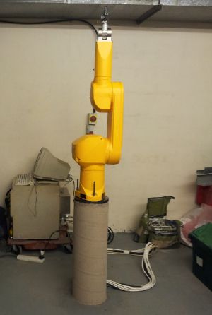
Kindly donated to us by Queen Mary's University, missing cable.
The plan is to Replace the cable and use the arm for 3d printing, precision welding/cutting, sculpting.
Applications
- Currently worked on
- 3D printing (Dependent on the G-code interpreter)
- CNC (Dependent on the G-code interpreter)
- PCB manufacture:
- Milling
- Drilling
- solder paste application for SMT components
- pick and place for SMT components
- Potential applications
- 3D scanning possibly using KinectFusion
- Persistence of vision experiments (such as this display at Trafalgar Square)
- High speed orbital photography
Status
Arm is able to interpret g-code. Some PCB milling has been done but can not control speed well currently and due to lack of a stationary table the positioning of the stock is tricky.
Specs
- Robot arm
- Type: RX60L
- Reference/machine number: 597411 - 01
- Fabrication Le F - 12 - 1997
- Masse kg 42Kg
- Controller
- Type CS7 - M RX60
- 3 x 400V - 50/60 Hz
- 4000VA
- Masse kg 80Kg
Some photos/videos of the beast
There is a 19 way cable running inside the arm, to allow external signals to be routed to the end effector. This uses a 19 way plug on the wrist joint and base called a Binder Connector.
TODO
- Build a smooth solid table surrounding the arm.
- Write the G-code interpreter for CNCing and 3d printing.
- Integrate the armpi with the controller better (power it from the 3 phase socket)
- Design and make the electronics for the controller to talk to the arm base (heated bed, calibration probe etc) and the end effector (spindle, extruder)
- Get/print the housings for the robot arm cable
- Hook up the arm to ROS
- Rewrite the ROS Industrial libraries to use a serial stream instead of IP+port combo
Write the ros serial server to run on the controller
Check and top up oil all the joints as per manual instructions 1st 5 axes:http://www.alexoil.co.uk/lumach-ep-gear-oil-iso-68--1l_p115.aspx Wrist:http://www.alexoil.co.uk/lumach-ep-gear-oils-iso-150--1l_p125.aspxReplace the battery 6v 8AH lead acid battery - this one: http://uk.rs-online.com/web/p/lead-acid-rechargeable-batteries/2651975/Install it in it's dedicated areaMake the cable from the arm (han-dd108m, han-dd72/han-K6/36 straight/angled) to the controllerDone 24/8/13 PadskiMake the cable for 3 phase power to controller.Make a mobile but stable platform for the robot and the controller (volunteers welcome)Thanks cepmender!!Get dummy plug for teaching pendant socket: Mouser Pt.Nos. # 571-66360-4 x 5 and # 571-2060371 x 1.
Docs
Robot startup/shutdown procedure
GZipped image of the 840MB drive
Technical manual with schematics
- Note Teaching Pendant connector needs pins 6+7 (estop), 14+16 (deadman) linked. DUMMY PLUG NOW MADE Padski 20-9-13 :)
Paper printed manual covering: General, arm, controller, controller options, spare parts
Another paper printed manual covering: Safety, robot coordinates, robot startup, editor, declaration of variables and conversions, commands associated to the main memory, some instructions of the V+ language, digital inputs/outputs, diskette or disc save operations, control of the robot configuration and specific commands, automatic startup-procedure, appendix (both of the manuals are in A4 folders, located in the library first column from the left, 3rd shelf from the top)
