Equipment/Dahlgren Wizzard 2000 ST: Difference between revisions
mNo edit summary |
No edit summary |
||
| Line 4: | Line 4: | ||
|model=Dahlgren Wizzard 2000 ST (heavily hacked) <!-- Model --> | |model=Dahlgren Wizzard 2000 ST (heavily hacked) <!-- Model --> | ||
|category=Equipment <!-- Main category. Please leave alone to keep item in this category --> | |category=Equipment <!-- Main category. Please leave alone to keep item in this category --> | ||
|subcat= | |subcat=defunct <!-- Sub-category if one exists. Please check main listing to see other categories contained within the main one --> | ||
|status= | |status=Unknown <!-- Set to one of; Good working order, Faulty, Out of order, Under construction, Out of consumables, Scrapped, or Unknown --> | ||
|consumables=Unknown <!-- Any items used up in normal operation, such as; ink, paper, saw-blades, cutting disks, oil, etc.. --> | |consumables=Unknown <!-- Any items used up in normal operation, such as; ink, paper, saw-blades, cutting disks, oil, etc.. --> | ||
|accessories=Unknown <!-- Any items associated with the equipment but not consumable, such as; drill bits, safety gloves, goggles, etc.. --> | |accessories=Unknown <!-- Any items associated with the equipment but not consumable, such as; drill bits, safety gloves, goggles, etc.. --> | ||
Latest revision as of 11:53, 21 January 2019
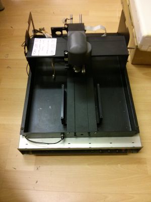
This is a project to convert a CNC engraver to also allow it to operate as a CNC pcb drill. The Engraver is a Dahlgren Wizzard 2000 ST. Currently, the engraver is actively worked on by Martin_p, and for the time being lives on the floor in the arts/crafts corner. The original roadmap/discussion has been moved to discussion for this page.
This wiki page is not written in a chronological order, and relevant sections will be updated as the work progresses. I am using my phone camera for taking the pictures, so please excuse their poor documentation-only quality. Please feel free to contact me with any suggestions, or correct any errors or omissions.
Resources
All resources, PCB designs and arduino C++ files live on GitHub. Feel free to look around and/or contribute (but please email me first).
Mechanics
Original state
Apart from lots of dirt and a bit of rust, the mechanical parts were in a reasonable order. The most important missing bits were:
- 3x NEMA 23 motors
- 2x 6mm flexible coupling
- z-axis pulley (6mm shaft)
- working bed
- main motor and belt between the rotary tool bit and the motor
- bit mounting mechanism (only a torso of it left)
Electronics
Original state
Electronics was split into 3 boards - driver/power source, a 386 controlling board and a front display/buttons board.
Driver board
The driver board was in a good shape, and seemed to be relatively easy to hack. The power source is 35V (motors) and 5V (electronics, stabilised), and works beautifully. The middle part contains a 6-phase motor driver, and will probably not end up used in the end. The stepper motor drivers are older versions, but fully functional, hardwired to use 1/10 substeps, and 800mA peak current.
Control board
The 386 machine refused to cooperate because of the missing main motor, and as it would be very hard to reverse-engineer it anyway, I went with the suggestion from the original discussion and ditched it.
Display/buttons board
The front board contains a set of buttons, a HD44780-compatible two lines LCD display and 3 pots, all in a very hackable working order.
Arduino
Pin assignment
| pin | meaning | |||
|---|---|---|---|---|
| serial | D0 | RX | ||
| D1 | TX | |||
| X+Y | D2 | step X | ||
| D3 | dir X | |||
| D4 | enable X+Y | |||
| D5 | step Y | |||
| D6 | dir Y | |||
| Z | D7 | enable Z | ||
| D8 | step Z | |||
| D9 | dir Z | |||
| D10 | piezo | shift reg | ||
| LCD | D11 | clk | 0 | RS |
| D12 | data | 1 | R/W | |
| D13 | strobe | 2 | clk | |
| 3 | (not connected) | |||
| 4 | bit 4 | |||
| 5 | bit 5 | |||
| 6 | bit 6 | |||
| 7 | bit 7 | |||
Software
All sources live on GitHub, both for Arduino and for Linux side (not yet implemented).
Original state
Because I decided to ditch the 386-based control board early on, the original state was non-existent.
Arduino
The main part of hard work is done by an Arduino Nano. It is connected directly to the motor drivers, endstops, display and buttons. It receives its data via a USB/RS232 serial port.


