Equipment/Staubli: Difference between revisions
mNo edit summary |
(Staubli base casting update) |
||
| Line 14: | Line 14: | ||
== Status == | == Status == | ||
Arm is now fully functional | Arm is now fully functional and the concrete base has been cast and is now drying 25-FEB-14<br> | ||
== Specs == | == Specs == | ||
Revision as of 17:49, 28 February 2014
| Staubli Robot arm | |
|---|---|
| Created | 07/06/2013 |
| Members | Mentar,Padski,tgreer,JonRussell |
| QR code | |
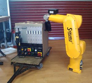
Kindly donated to us by Queen Mary's University, missing cable.
The plan is to Replace the cable and use the arm for 3d printing, precision welding/cutting, sculpting.
Status
Arm is now fully functional and the concrete base has been cast and is now drying 25-FEB-14
Specs
- Robot arm
- Type: RX60L
- Reference/machine number: 597411 - 01
- Fabrication Le F - 12 - 1997
- Masse kg 42Kg
- Controller
- Type CS7 - M RX60
- 3 x 400V - 50/60 Hz
- 4000VA
- Masse kg 80Kg
Some photos/videos of the beast
TODO
- Check and top up oil all the joints as per manual instructions 1st 5 axes:http://www.alexoil.co.uk/lumach-ep-gear-oil-iso-68--1l_p115.aspx Wrist:http://www.alexoil.co.uk/lumach-ep-gear-oils-iso-150--1l_p125.aspx
- Replace the battery 6v 8AH lead acid battery
- Get/print the housings for the robot arm cable
- Figure out how to do useful things with it!
- Install it in it's dedicated area
Make the cable from the arm (han-dd108m, han-dd72/han-K6/36 straight/angled) to the controllerDone 24/8/13 PadskiMake the cable for 3 phase power to controller.Make a mobile but stable platform for the robot and the controller (volunteers welcome)Thanks cepmender!!Get dummy plug for teaching pendant socket: Mouser Pt.Nos. # 571-66360-4 x 5 and # 571-2060371 x 1.
Docs
Robot startup/shutdown procedure
GZipped image of the 840MB drive
Technical manual with schematics
- Note Teaching Pendant connector needs pins 6+7 (estop), 14+16 (deadman) linked. DUMMY PLUG NOW MADE Padski 20-9-13 :)
Paper printed manual covering: General, arm, controller, controller options, spare parts
Another paper printed manual covering: Safety, robot coordinates, robot startup, editor, declaration of variables and conversions, commands associated to the main memory, some instructions of the V+ language, digital inputs/outputs, diskette or disc save operations, control of the robot configuration and specific commands, automatic startup-procedure, appendix (both of the manuals are in A4 folders, located in the library first column from the left, 3rd shelf from the top)
