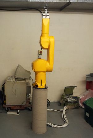
Equipment/Staubli
Kindly donated to us by Queen Mary's University, was missing arm and power cables.
The arm is being worked on by the robotics group (more help welcome) and the plan is to turn it into a cnc/3d printer/plasma cutting machine and open up to the general membership once safe to do so.
Applications
- Potential applications
- 3D scanning possibly using KinectFusion
- Persistence of vision experiments (such as this display at Trafalgar Square)
- High speed orbital photography
- CNC (Dependent on the G-code interpreter)
- PCB manufacture:
- Milling
- Drilling
- solder paste application for SMT components
- pick and place for SMT components
- Currently worked on
Status
The arm is currently a work in progress. It is driven by an open source controller but we still need to complete the kinematics for it
Specs
- Robot arm
- Type: RX60L
- Reference/machine number: 597411 - 01
- Fabrication Le F - 12 - 1997
- Masse kg 42Kg
- Controller
- Type CS7 - M RX60
- 3 x 400V - 50/60 Hz
- 4000VA
- Masse kg 80Kg
- STMBL
- Type 4.1
- The STMBL along with Messa cards driven by linuscnc have been used to control the arm, massive support has been received from the open source community (STMBL and LinuxCNC) as well as Messa who did a custom firmware reactivity for us while we were having a hack weekend - great international and multidisciplinary team work.
Some photos/videos of the beast
There is a 19 way cable running inside the arm, to allow external signals to be routed to the end effector. This uses a 19 way plug on the wrist joint and base called a Binder Connector.
There is a 50 way connector (J11) at the back of the controller containing the digital IO lines.
TODO
- Necessary
Build a smooth solid table surrounding the arm.
- Nice to have
Document .
Docs/Links
Robot startup/shutdown procedure
GZipped image of the 840MB drive
Technical manual with schematics
- Note Teaching Pendant connector needs pins 6+7 (estop), 14+16 (deadman) linked. DUMMY PLUG NOW MADE Padski 20-9-13 :)
Paper printed manual covering: General, arm, controller, controller options, spare parts
Another paper printed manual covering: Safety, robot coordinates, robot startup, editor, declaration of variables and conversions, commands associated to the main memory, some instructions of the V+ language, digital inputs/outputs, diskette or disc save operations, control of the robot configuration and specific commands, automatic startup-procedure, appendix (both of the manuals are in A4 folders, located in the library first column from the left, 3rd shelf from the top)
