Difference between revisions of "Denford CNC 2600"
Deanforbes (talk | contribs) |
|||
| (29 intermediate revisions by 2 users not shown) | |||
| Line 12: | Line 12: | ||
|origin=Donation | |origin=Donation | ||
|location=Ground Floor, Woodshop | |location=Ground Floor, Woodshop | ||
| − | |maintainers= | + | |maintainers=Jonathan |
}} | }} | ||
| − | ===== | + | ===== Next steps ===== |
| − | * | + | *Install MESA |
| − | * | + | *Configure Linuxcnc |
| − | + | ||
| − | |||
| − | |||
| − | |||
| − | |||
| − | |||
| − | |||
| − | |||
| − | |||
| − | |||
| − | |||
| − | |||
| − | |||
| − | |||
| − | |||
| − | |||
| − | |||
| − | |||
| − | |||
| − | |||
| − | |||
| − | |||
| − | |||
** dust extraction | ** dust extraction | ||
There is a hole at the top rear left of the cabinet which may be used for dust extraction - either a separate unit or a connection to the shop extractor. However, the cutting dust tends to lie around the cutter so some means to move it to the extraction is required. Possibilities are throwing it into the air and then extracting the air, or sucking directly at the cutting tip. There is a small air pump in the cabinet whose output is taken to a connector under the gantry parking position. This may be used to disturb the air near the cutter, and a flexible hose to the extraction used to remove it. The hoses needed may get in the way : this requires some experiment. A dust shoe may be helpful but will hide the cutting point from view. | There is a hole at the top rear left of the cabinet which may be used for dust extraction - either a separate unit or a connection to the shop extractor. However, the cutting dust tends to lie around the cutter so some means to move it to the extraction is required. Possibilities are throwing it into the air and then extracting the air, or sucking directly at the cutting tip. There is a small air pump in the cabinet whose output is taken to a connector under the gantry parking position. This may be used to disturb the air near the cutter, and a flexible hose to the extraction used to remove it. The hoses needed may get in the way : this requires some experiment. A dust shoe may be helpful but will hide the cutting point from view. | ||
| + | *Prepare Inductions | ||
*AC Node | *AC Node | ||
| Line 64: | Line 43: | ||
*[[File:MRP-0850_ESTOP_relay_contacts.pdf]] | *[[File:MRP-0850_ESTOP_relay_contacts.pdf]] | ||
*Schematic design B (Note we have version A so there maybe some differences) [[File:Schematic_Design_MRP-0850B.pdf]] | *Schematic design B (Note we have version A so there maybe some differences) [[File:Schematic_Design_MRP-0850B.pdf]] | ||
| + | *[[Cabinet Wiring]] | ||
===== Manuals ===== | ===== Manuals ===== | ||
| + | *Spindle VFD [[File:Baldor-VS1ST-Micro-Series-Manual.pdf]] | ||
| + | *Stepper drive [[File:MSD556-V2.0 stepper-drive-datasheet-v3.0.pdf]] | ||
| + | ====== Obsolete manuals for reference ====== | ||
*User Manual [[File:Router_2600_Pro_Operator_Manual.pdf]] | *User Manual [[File:Router_2600_Pro_Operator_Manual.pdf]] | ||
*VR CNC Control Software v5 Training Guide [[File:VR_Milling_5.pdf]] | *VR CNC Control Software v5 Training Guide [[File:VR_Milling_5.pdf]] | ||
| + | *Some notes on the Baldor Nextmove controller originally fitted [https://www.denfordata.com/bb/viewtopic.php?f=54&t=2264] | ||
| + | *Manual for the original Nextmove ST controller [[File:NextmoveST-Installation-Guide.pdf]] - this has an additional top board which adds DSP movement control and replaces the built-in stepper drives with external drives | ||
===== MESA 7i76 ===== | ===== MESA 7i76 ===== | ||
| − | *7i76e Manual [[File: | + | *7i76e Manual [[File:7i76eman.pdf]] |
*7i76e Connection Guide [[File:7i76_Con_Guide.pdf]] | *7i76e Connection Guide [[File:7i76_Con_Guide.pdf]] | ||
| + | *7i76e Mounting Base [[File:7i76E mounting base 2.pdf]] | ||
| + | *May be useful - https://jethornton.github.io/7i76e/install.html | ||
| + | |||
| + | Mesa board outline | ||
| + | |||
| + | Adapter plate to fit Baldor mounts | ||
| + | |||
| + | [[File:7i76 adapter plate.svg]] | ||
| + | |||
| + | Adapter plate is 262x140 with cabinet mounting holes at 132x212, 20 from LHS and 30 from RHS | ||
| + | Mesa board to be at LHS of space. Note that Mesa board outline includes connector space | ||
===== Linuxcnc ===== | ===== Linuxcnc ===== | ||
| − | + | '''To do''' | |
| + | |||
| + | *Install Linuxcnc | ||
| + | *Instal Nativecam (a component of linuxcnc) - gives conversational CNC capability | ||
| + | *Create GITHUB Repository | ||
| + | |||
| + | '''Resources''' | ||
| + | |||
| + | *https://www.machinekit.io/docs/hal/intro/ | ||
| + | *http://linuxcnc.org/2022/03/03/LinuxCNC-in-Debian/ | ||
Latest revision as of 12:50, 17 September 2022
| Denford CNC | |
|---|---|
 | |
| Model | 2600 pro |
| Sub-category | CNC |
| Status | View tool status |
| Last updated | 17 September 2022 12:50:55 |
| Training requirement | yes |
| Training link | cnc_denford_2600_training |
| ACnode | not yet |
| Owner | LHS |
| Origin | Donation |
| Location | Ground Floor, Woodshop |
| Maintainers | Jonathan |
Next steps
- Install MESA
- Configure Linuxcnc
- dust extraction
There is a hole at the top rear left of the cabinet which may be used for dust extraction - either a separate unit or a connection to the shop extractor. However, the cutting dust tends to lie around the cutter so some means to move it to the extraction is required. Possibilities are throwing it into the air and then extracting the air, or sucking directly at the cutting tip. There is a small air pump in the cabinet whose output is taken to a connector under the gantry parking position. This may be used to disturb the air near the cutter, and a flexible hose to the extraction used to remove it. The hoses needed may get in the way : this requires some experiment. A dust shoe may be helpful but will hide the cutting point from view.
- Prepare Inductions
- AC Node
Collets
- We are using ER 20 collets
- You will need to provide your own tooling
- Use of collets ER Collet Essentials. https://www.youtube.com/watch?v=WKikm6cQKh0
Training and induction s
TBD
Materials
- This is in the woodshop and to be used on non metal materials only.
- No liquid or mist coolant is to be used in the machine at all.
Schematics
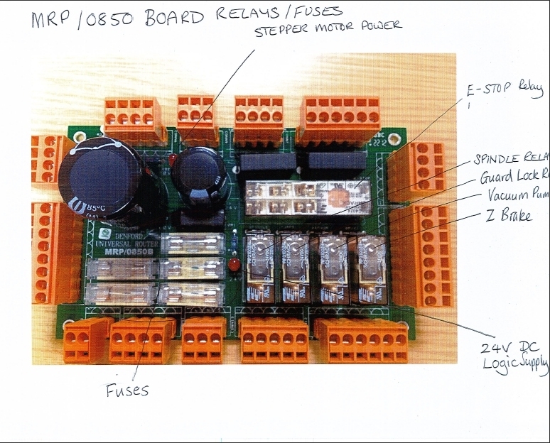
- File:MRP-0850 ESTOP relay contacts.pdf
- Schematic design B (Note we have version A so there maybe some differences) File:Schematic Design MRP-0850B.pdf
- Cabinet Wiring

Manuals
- Spindle VFD File:Baldor-VS1ST-Micro-Series-Manual.pdf
- Stepper drive File:MSD556-V2.0 stepper-drive-datasheet-v3.0.pdf
Obsolete manuals for reference
- User Manual File:Router 2600 Pro Operator Manual.pdf
- VR CNC Control Software v5 Training Guide File:VR Milling 5.pdf
- Some notes on the Baldor Nextmove controller originally fitted [1]
- Manual for the original Nextmove ST controller File:NextmoveST-Installation-Guide.pdf - this has an additional top board which adds DSP movement control and replaces the built-in stepper drives with external drives
MESA 7i76
- 7i76e Manual File:7i76eman.pdf
- 7i76e Connection Guide File:7i76 Con Guide.pdf
- 7i76e Mounting Base File:7i76E mounting base 2.pdf
- May be useful - https://jethornton.github.io/7i76e/install.html
Mesa board outline
Adapter plate to fit Baldor mounts

Adapter plate is 262x140 with cabinet mounting holes at 132x212, 20 from LHS and 30 from RHS
Mesa board to be at LHS of space. Note that Mesa board outline includes connector space
Linuxcnc
To do
- Install Linuxcnc
- Instal Nativecam (a component of linuxcnc) - gives conversational CNC capability
- Create GITHUB Repository
Resources