Difference between revisions of "Equipment/Staubli"
Deanforbes (talk | contribs) |
Deanforbes (talk | contribs) (→Status) |
||
| (4 intermediate revisions by the same user not shown) | |||
| Line 15: | Line 15: | ||
}} | }} | ||
__NOTOC__ | __NOTOC__ | ||
| − | Kindly donated to us by Queen Mary University's School of Electronic Engineering & Computer Science was missing arm and power cables. | + | Kindly donated to us by Queen Mary University's School of Electronic Engineering & Computer Science was missing arm and power cables. |
| + | A copy of the original cable was made and used until the failure of the controller - it was then scrapped | ||
| + | A generic one was then made up using RJ45 for the encoder cables and SPECON for the servo motors themselves | ||
== Status == | == Status == | ||
| − | + | retired and scrapped | |
<br> | <br> | ||
== Specs == | == Specs == | ||
| + | |||
| + | It was driven by an open source controller due to failure of the original controller | ||
| + | |||
* Robot arm | * Robot arm | ||
** Type: RX60L | ** Type: RX60L | ||
| Line 31: | Line 36: | ||
* STMBL | * STMBL | ||
** Type 4.1 | ** Type 4.1 | ||
| − | ** The STMBL along with Messa cards driven by | + | ** The STMBL along with Messa cards driven by linuxcnc have been used to control the arm, massive support has been received from the open source community (STMBL and LinuxCNC) as well as Messa who did a custom firmware reactivity for us while we were having a hack weekend - great international and multidisciplinary team work. |
<gallery> | <gallery> | ||
| Line 44: | Line 49: | ||
There is a 19 way cable running inside the arm, to allow external signals to be routed to the end effector. This uses a 19 way plug on the wrist joint and base called a [[Equipment/Staubli/BinderConnector|Binder Connector]]. | There is a 19 way cable running inside the arm, to allow external signals to be routed to the end effector. This uses a 19 way plug on the wrist joint and base called a [[Equipment/Staubli/BinderConnector|Binder Connector]]. | ||
| − | |||
| − | |||
| − | |||
| − | |||
| − | |||
| − | |||
| − | |||
| − | |||
| − | |||
== Docs/Links == | == Docs/Links == | ||
Latest revision as of 21:26, 4 August 2022
| Staubli robot arm | |
|---|---|
 | |
| Model | RX60L |
| Sub-category | Robotics |
| Status | retired and scrapped |
| Last updated | 4 August 2022 21:26:32 |
| Training requirement | None |
| ACnode | no |
| Owner | Robotics group |
| Origin | Donation |
Kindly donated to us by Queen Mary University's School of Electronic Engineering & Computer Science was missing arm and power cables. A copy of the original cable was made and used until the failure of the controller - it was then scrapped A generic one was then made up using RJ45 for the encoder cables and SPECON for the servo motors themselves
Status
retired and scrapped
Specs
It was driven by an open source controller due to failure of the original controller
- Robot arm
- Type: RX60L
- Reference/machine number: 597411 - 01
- Fabrication Le F - 12 - 1997
- Masse kg 42Kg
- STMBL
- Type 4.1
- The STMBL along with Messa cards driven by linuxcnc have been used to control the arm, massive support has been received from the open source community (STMBL and LinuxCNC) as well as Messa who did a custom firmware reactivity for us while we were having a hack weekend - great international and multidisciplinary team work.
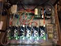
STMBL Case

Hackspace, STMBL and Linuxcnc Team


We have movement https://flic.kr/p/21GzpWj
Some photos/videos of the beast
There is a 19 way cable running inside the arm, to allow external signals to be routed to the end effector. This uses a 19 way plug on the wrist joint and base called a Binder Connector.
Docs/Links
Robot startup/shutdown procedure