Difference between revisions of "Project:USB Disco Dance Floor/v1"
(I want the full QR code on this page) |
(Updated project log) |
||
| (16 intermediate revisions by the same user not shown) | |||
| Line 1: | Line 1: | ||
| − | __NOEDITSECTION__{{Project|name=USB Disco Dance Floor|version=1|members=[[User:dmi|DMI]]|created=2011-03-31|status=Prototyping | + | __NOEDITSECTION__{{Project|name=USB Disco Dance Floor|version=1|members=[[User:dmi|DMI]]|created=2011-03-31|status=Prototyping}} |
== Introduction == | == Introduction == | ||
| + | [[File:DDF-MIT.jpg|240|thumb|right|Something like what I aim to accomplish]] | ||
The aim of this project is to create a USB-controlled, Arudino-powered 70's-style disco dance floor, inspired by a [http://www.scotttorborg.com/disco-dance-floor/ similar project] by a student at MIT. It will act as a modular, low-resolution RGB display. Each pixel will be 6-8" per side, and it will come in 4x4-pixel modules that can be connected together. | The aim of this project is to create a USB-controlled, Arudino-powered 70's-style disco dance floor, inspired by a [http://www.scotttorborg.com/disco-dance-floor/ similar project] by a student at MIT. It will act as a modular, low-resolution RGB display. Each pixel will be 6-8" per side, and it will come in 4x4-pixel modules that can be connected together. | ||
| − | The board, firmware, and software will (of course) be open-sourced. | + | The board, [[{{FULLPAGENAME}}/firmware|firmware]], and controller software will (of course) be open-sourced. |
=== Terminology === | === Terminology === | ||
| Line 11: | Line 12: | ||
Each pixel will be referred to as a ''cell'', and each self-contained block of 4x4 pixels will be referred to as a ''module''. | Each pixel will be referred to as a ''cell'', and each self-contained block of 4x4 pixels will be referred to as a ''module''. | ||
| − | == Materials == | + | == Construction == |
| + | |||
| + | === Prototype === | ||
| + | |||
| + | The prototype is just a small bit of veroboard (in fact, slightly too small... it is one hole shorter than I really wanted!) with the traces cut between holes using a Dremel. | ||
| + | |||
| + | === Materials === | ||
I plan for the main body of the module to be made of wood, with some sort of frosted/diffused acrylic top. It needs to be strong enough to handle a relatively large number of people jumping up and down on it, as well as potentially spilling drinks etc. | I plan for the main body of the module to be made of wood, with some sort of frosted/diffused acrylic top. It needs to be strong enough to handle a relatively large number of people jumping up and down on it, as well as potentially spilling drinks etc. | ||
| Line 17: | Line 24: | ||
== Project log == | == Project log == | ||
| + | [[File:DDF-front-20110403.jpg|240|thumb|right|Top of prototype, as of 2011-04-03]][[File:DDF-back-20110403.jpg|240|thumb|right|Bottom of prototype, as of 2011-04-03]] | ||
;2011-03-29: | ;2011-03-29: | ||
:*I am building the prototype circuit on veroboard: one 4x4 array of [http://www.earthshineelectronics.com/optoelectronics/55-pirahna-rgb-led-pack-of-10.html RGB Piranha LEDs], plus three [http://www.earthshineelectronics.com/integrated-circuits/62-tlc5940-16-channel-led-driver.html TLC5940] drivers. | :*I am building the prototype circuit on veroboard: one 4x4 array of [http://www.earthshineelectronics.com/optoelectronics/55-pirahna-rgb-led-pack-of-10.html RGB Piranha LEDs], plus three [http://www.earthshineelectronics.com/integrated-circuits/62-tlc5940-16-channel-led-driver.html TLC5940] drivers. | ||
:*I have yet to decide whether the ICs will be assigned one per colour or just sequentially tie the outputs to the LED pins. I should be able to get 4096 levels per output channel, so this gives me (apparently) 68.7 ''billion'' colours per pixel (4096³), which should probably be enough. I'll probably reduce that down to the more standard 256 levels. | :*I have yet to decide whether the ICs will be assigned one per colour or just sequentially tie the outputs to the LED pins. I should be able to get 4096 levels per output channel, so this gives me (apparently) 68.7 ''billion'' colours per pixel (4096³), which should probably be enough. I'll probably reduce that down to the more standard 256 levels. | ||
:*A quick test on breadboard showed that I can at least control one TLC5940 and 5 LEDs as expected, with a sweeping pattern across the outputs. Next stage is doing exactly the same on the veroboard prototype! | :*A quick test on breadboard showed that I can at least control one TLC5940 and 5 LEDs as expected, with a sweeping pattern across the outputs. Next stage is doing exactly the same on the veroboard prototype! | ||
| + | ;2011-04-03: | ||
| + | :*I have finished soldering the LED array onto the board, including resistors, and I have now made a start on wiring the LEDs to the controllers. I also connected all of the common anodes | ||
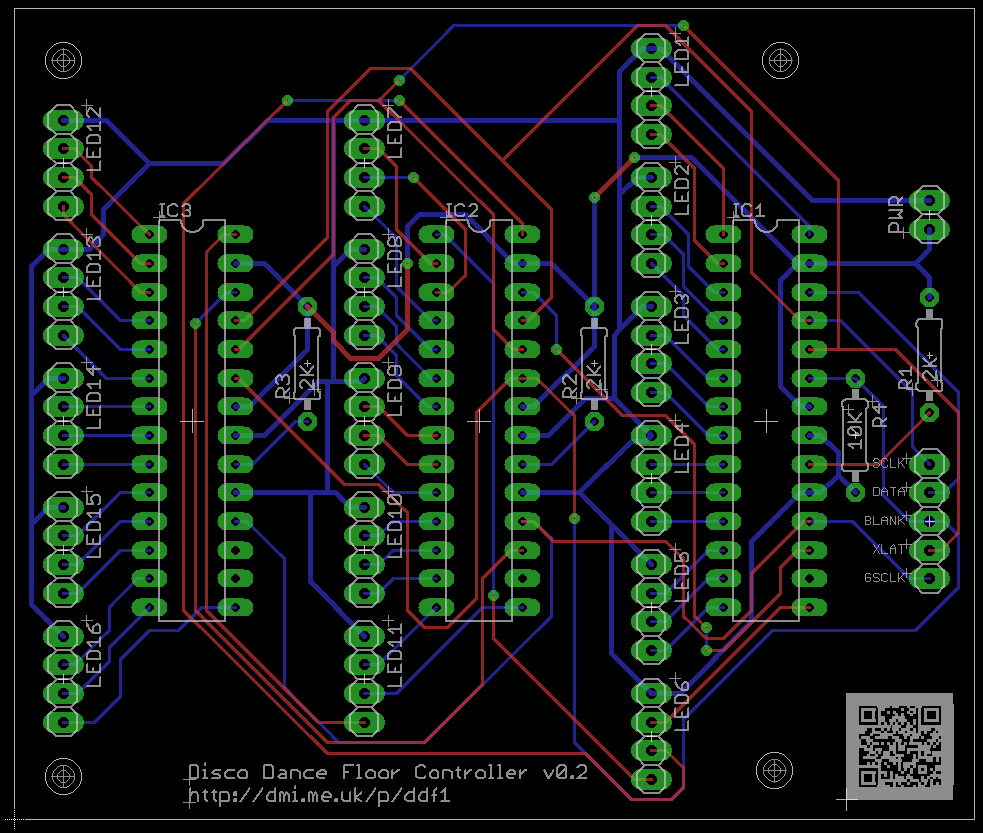
| + | :*I decided to connect the LEDs to the drivers sequentially, so R0 -> OUT00, G0 -> OUT01, B1 -> OUT02, etc. This was partially prompted by designing [[Media:DDF-PCB-v1-20110403.png|a PCB]] for future use. I hope to have a prototype of the board produced professionally by [http://www.spiritcircuits.com/services/go-naked Spirit Circuits' Go Naked service], so I can test and refine it. A future version of the board will have the microcontroller embedded (as described below), or ''possibly'' done as an Arduino shield. Turning it into a shield is unlikely, however: the board would be quite large, and routing might be complex. It would likely be more than my version of Eagle can handle! | ||
| + | ;2011-04-10: | ||
| + | :*The prototype PCB has arrived, but I'm not sure it will be the final design. Might be worth playing with, however. Perhaps I will solder it with chip holders instead of soldering the chips directly. | ||
| + | :*I have also considered the merits of having an onboard 4-port USB 1.1 hub and thinking about autodetecting module relative position and orientation | ||
| + | ;2011-04-12: | ||
| + | :*I finished soldering the required pins for the first chip's connection to the Arduino, which means that in theory the first five LEDs could be controlled correctly. I just have to wire them in! | ||
| + | ;2011-04-14: | ||
| + | [[File:DDF-PCB-v1-soldered-top.jpg|thumb|right|Top of PCB prototype, as of 2011-04-14]][[File:DDF-PCB-v1-soldered-bottom.jpg|thumb|right|Bottom of PCB prototype, as of 2011-04-14]] | ||
| + | :*First version of the firmware written, but untested. | ||
| + | :*Bother. After soldering in the connections for the first four LEDs, there was a problem with LED2: no matter what the firmware specified, it would be full-brightness green. It appears to be a problem with the chip itself, so something needed to be done. | ||
| + | :*Ended up soldering the PCB (with help from [[User:Samthetechie|Samthetechie]]) and currently awaiting spare TLC5940s to arrive from TI. I love their "free sample" service! I also plan to redesign the PCB to be smaller and use smaller trace widths, as well as reorganise a couple of components. | ||
| + | ;2011-04-15: | ||
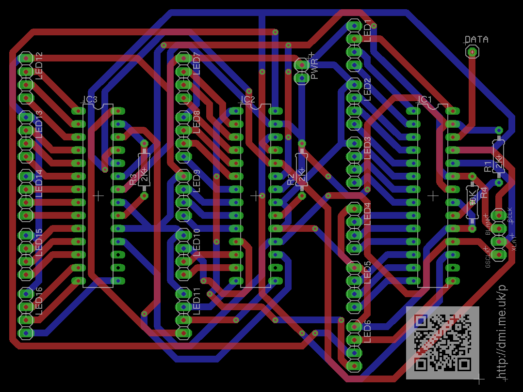
| + | :*Redesigned [[Media:DDF-PCB-v0.2-20110415.png|the PCB]] as described above and ordered a prototype from [http://www.spiritcircuits.com/services/go-naked Spirit Circuits] again. This board should be more solder-friendly due to thinner traces (smaller thermal area) and copper hints about what goes where. As another new feature, this board has mounting holes set at the corners of a 2.5" square. The board itself is 3.35" by 2.83". With luck, I should be able to fit 12 of these on a 1sqft panel via [http://myworld.ebay.co.uk/spirit-electronics Spirit Circuits' eBay store], so each PCB would cost in the region of £2. | ||
| + | ;2011-04-19: | ||
| + | :*Soldered the rest of the LEDs, with some help from Sam (another one) and [[User:elliot_w|elliot_w]]. | ||
| + | ;2011-04-20: | ||
| + | :*'''IT WORKS!''' ... more or less. Some of the LED channels aren't working, but that seems to be just down to dodgy wiring. | ||
| + | |||
| + | <br style="clear: right"> | ||
== Future directions == | == Future directions == | ||
| − | [[{{#titleparts:{{FULLPAGENAME}}|-1}}|Version 2]] of this project will provide RGB+UV for each cell, with pressure sensors. Ideally the pressure sensors will have a resolution of one cell, so that the floor could be used for games (e.g. Tetris or a mash-up of Dance Dance Revolution and Guitar Hero). The Arduinos (or other microcontrollers) will be embedded into the board design, and the PCBs batch-produced. | + | [[File:Ddf-ddr-concept.gif|thumb|right|Dance Dance Revolution/Guitar Hero mashup concept]] |
| + | [[{{#titleparts:{{FULLPAGENAME}}|-1}}|Version 2]] of this project will provide RGB+UV for each cell, with pressure sensors. Ideally the pressure sensors will have a resolution of one cell, so that the floor could be used for games (e.g. Tetris or a mash-up of Dance Dance Revolution and Guitar Hero). The Arduinos (or other microcontrollers) will be embedded into the board design, and the PCBs batch-produced. The board will also have a [http://uk.farnell.com/texas-instruments/tusb2046bvf/ic-usb-hub-4-port-32lqfp/dp/1470507 4-port USB hub] built into it, for inter-module communication. | ||
| − | Note: Tetris requires 10px wide by 20 high. DDR would require ((NPlayers * 5) - 1)px. It looks like the floor would have to therefore be a minimum of | + | Note: Tetris requires 10px wide by 20 high for the playing field. DDR would require ((NPlayers * 5) - 1)px wide. It looks like the floor would have to therefore be a minimum of 3x8 modules for Tetris, and probably the same for DDR (but perhaps shorter). For two players, DDR requires a minimum of 3 modules wide, but the height could be relatively variable. The example floor to the right is 3x7 modules. |
Latest revision as of 12:14, 21 April 2011
| USB Disco Dance Floor | |
|---|---|
| Created | 2011-03-31 |
| Version | 1 |
| Members | DMI |
| Project Status | Prototyping |
| QR code | |
Introduction

The aim of this project is to create a USB-controlled, Arudino-powered 70's-style disco dance floor, inspired by a similar project by a student at MIT. It will act as a modular, low-resolution RGB display. Each pixel will be 6-8" per side, and it will come in 4x4-pixel modules that can be connected together.
The board, firmware, and controller software will (of course) be open-sourced.
Terminology
Each pixel will be referred to as a cell, and each self-contained block of 4x4 pixels will be referred to as a module.
Construction
Prototype
The prototype is just a small bit of veroboard (in fact, slightly too small... it is one hole shorter than I really wanted!) with the traces cut between holes using a Dremel.
Materials
I plan for the main body of the module to be made of wood, with some sort of frosted/diffused acrylic top. It needs to be strong enough to handle a relatively large number of people jumping up and down on it, as well as potentially spilling drinks etc.
Project log


- 2011-03-29
-
- I am building the prototype circuit on veroboard: one 4x4 array of RGB Piranha LEDs, plus three TLC5940 drivers.
- I have yet to decide whether the ICs will be assigned one per colour or just sequentially tie the outputs to the LED pins. I should be able to get 4096 levels per output channel, so this gives me (apparently) 68.7 billion colours per pixel (4096³), which should probably be enough. I'll probably reduce that down to the more standard 256 levels.
- A quick test on breadboard showed that I can at least control one TLC5940 and 5 LEDs as expected, with a sweeping pattern across the outputs. Next stage is doing exactly the same on the veroboard prototype!
- 2011-04-03
-
- I have finished soldering the LED array onto the board, including resistors, and I have now made a start on wiring the LEDs to the controllers. I also connected all of the common anodes
- I decided to connect the LEDs to the drivers sequentially, so R0 -> OUT00, G0 -> OUT01, B1 -> OUT02, etc. This was partially prompted by designing a PCB for future use. I hope to have a prototype of the board produced professionally by Spirit Circuits' Go Naked service, so I can test and refine it. A future version of the board will have the microcontroller embedded (as described below), or possibly done as an Arduino shield. Turning it into a shield is unlikely, however: the board would be quite large, and routing might be complex. It would likely be more than my version of Eagle can handle!
- 2011-04-10
-
- The prototype PCB has arrived, but I'm not sure it will be the final design. Might be worth playing with, however. Perhaps I will solder it with chip holders instead of soldering the chips directly.
- I have also considered the merits of having an onboard 4-port USB 1.1 hub and thinking about autodetecting module relative position and orientation
- 2011-04-12
-
- I finished soldering the required pins for the first chip's connection to the Arduino, which means that in theory the first five LEDs could be controlled correctly. I just have to wire them in!
- 2011-04-14


- First version of the firmware written, but untested.
- Bother. After soldering in the connections for the first four LEDs, there was a problem with LED2: no matter what the firmware specified, it would be full-brightness green. It appears to be a problem with the chip itself, so something needed to be done.
- Ended up soldering the PCB (with help from Samthetechie) and currently awaiting spare TLC5940s to arrive from TI. I love their "free sample" service! I also plan to redesign the PCB to be smaller and use smaller trace widths, as well as reorganise a couple of components.
- 2011-04-15
-
- Redesigned the PCB as described above and ordered a prototype from Spirit Circuits again. This board should be more solder-friendly due to thinner traces (smaller thermal area) and copper hints about what goes where. As another new feature, this board has mounting holes set at the corners of a 2.5" square. The board itself is 3.35" by 2.83". With luck, I should be able to fit 12 of these on a 1sqft panel via Spirit Circuits' eBay store, so each PCB would cost in the region of £2.
- 2011-04-19
-
- Soldered the rest of the LEDs, with some help from Sam (another one) and elliot_w.
- 2011-04-20
-
- IT WORKS! ... more or less. Some of the LED channels aren't working, but that seems to be just down to dodgy wiring.
Future directions

Version 2 of this project will provide RGB+UV for each cell, with pressure sensors. Ideally the pressure sensors will have a resolution of one cell, so that the floor could be used for games (e.g. Tetris or a mash-up of Dance Dance Revolution and Guitar Hero). The Arduinos (or other microcontrollers) will be embedded into the board design, and the PCBs batch-produced. The board will also have a 4-port USB hub built into it, for inter-module communication.
Note: Tetris requires 10px wide by 20 high for the playing field. DDR would require ((NPlayers * 5) - 1)px wide. It looks like the floor would have to therefore be a minimum of 3x8 modules for Tetris, and probably the same for DDR (but perhaps shorter). For two players, DDR requires a minimum of 3 modules wide, but the height could be relatively variable. The example floor to the right is 3x7 modules.